OTS FT100-SMR Installation And Operation Manual Download Page 8

FT100 Series Installation & Operation Manual 


www.ot-systems.com


3.3  Card module installation 

a) 

Insert the card module into the FT-C18 chassis along the top and bottom card guides of an 

empty slot and push the card into the multi-pin socket at the rear firmly. Secure with the provided 

thumb screws.   

b) 

Repeat the above procedure for all the rest card modules. Unused slots must be covered 

with blank panels provided. 

c) 

Connect  all  the  signal  inputs  and  outputs  at  the  back  of  the  unit  with  appropriate  cables: 

fiber optic cable for optical link, BNC cable for video input/output (Tx/Rx).   

d) 

Once  the  chassis  is  powered  up,  check  that  the  red  POWER  LED  on  the  front  and  back 

panels of the card modules are lit. If not, check the power supply cable connections between the 

chassis and the power supply socket. For failures of individual card’s POWER LEDs, check the 

corresponding card modules, whether they have been inserted properly. 

e) 

With all the signals available at the input and output ports, check the status of LEDs located 

on the unit

.

 With correct status of each LED, installation is now completed [for LEDs status, see 

Operational Guides


on this manual’s section 

(5)

]. 


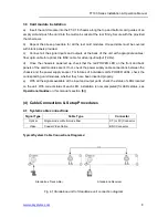
(4)  Cable Connections & Setup Procedures 

4.1  System cable connections 

Signal Type 

Cable Type   

Connector 

Optical 

Single-mode or Multi-mode fiber 

ST (or FC) Connector 

Video 

Coaxial Video Cable 

BNC Connector 


Typical System Cable Connections Diagrams: 


Standalone Transmitter     


Standalone Receiver 


Fig 4.1 

Standalone unit to Standalone unit connection diagram 


Summary of Contents for FT100-SMR

Page 1: ...FT100 Series Installation Operation Manual www ot systems com 1 Installation and Operation Manual FT100 Series 10 bit Digital Series 1 ch Video Fiber Optic Converter OT Systems Ltd 2014 Rev 1 2...

Page 2: ...ode Receivers FT100 SSRSA FT100 SSRLSA Multi Mode Transmitter FT100 SMTSA Multi Mode Receiver FT100 SMRSA Card Modules Single Mode Transmitters FT100 SST FT100 SSTL Single Mode Receivers FT100 SSR FT1...

Page 3: ...ABLE 6 3 INSTALLATION 7 3 1 GENERAL 7 3 2 STANDALONE UNIT INSTALLATION 7 3 3 CARD MODULE INSTALLATION 8 4 CABLE CONNECTIONS SETUP PROCEDURES 8 4 1 SYSTEM CABLE CONNECTIONS 8 4 2 GROUND CONNECTION 10 5...

Page 4: ...Class I invisible optical radiation is possible when the internal fiber optic connector is disconnected while the unit is powered up Caution Any access to the controls adjustments or performing operat...

Page 5: ...y is employed for digital transmission of forward video For single mode transmission we also offer specifically designed products for long haul transmissions up to 60km These models include the letter...

Page 6: ...ode FT100 SMTSA Multi mode 1 Ch Video Transmitter Standalone Unit FT100 SMRSA Multi mode 1 Ch Video Receiver Standalone Unit Card Modules Single Mode FT100 SST Single mode 1 Ch Video Transmitter Card...

Page 7: ...d a total of 18 cards can be housed inside the chassis 3 2 Standalone unit installation a Mount the standalone unit onto a fixture either on the wall or on a flat surface with four screws through the...

Page 8: ...ront and back panels of the card modules are lit If not check the power supply cable connections between the chassis and the power supply socket For failures of individual card s POWER LEDs check the...

Page 9: ...ion Manual www ot systems com 9 Standalone Transmitter Card Module Receiver Fig 4 2 Standalone unit to Card Module connection diagram Card Module Transmitter Card Module Receiver Fig 4 3 Card Module t...

Page 10: ...used by lightning and other power surges as well as a connection to the surge suppresion devices in the product a screw terminal is provided on the Standalone cabinets Fig 4 4 It is highly recommended...

Page 11: ...the OL LED on the Tx is not lit because optical signal from the Rx to the Tx is always inactive Signal Ports OPT ST or FC Optical Connector for fiber cable connection VIDEO IN BNC Video Connector for...

Page 12: ...Impedance 75 Ohm Input Output Level 1 0 Vp p typical Differential Gain 1 typical Differential Phase 1 o typical SNR 65dB POWER Power consumption 12VDC 3W Power Supply Standalone Unit FT PA12V DC Adap...

Page 13: ...lone unit mm 8 Warranty Information All OT Systems FT Series products are subject to a limited life time warranty offered by the company in normal circumstances Please refer to the OT Systems Products...

Page 14: ...s ot systems com Technical Support techsupport ot systems com EMEA Operation Address J Slovackio str 4 LT 11107 Vilnius Lithuania Tel 370 60730087 Fax 370 52051855 Sales Inquiries sales ot systems com...

Reviews: