38
OticOn Agil
FITTING GUIDE
39
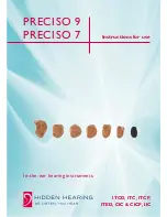
custom Mold
A Micro Mold is an option for Corda
2
solutions on BTE 13.
Additional Rite Molds are also available in e.g. canal lock and
skeleton canal for improved retention, when necessary.
Micro Molds in all shapes or canal Molds are produced from
a traditional, deep impression.
Micro Mold
Canal Lock
Skeleton Canal
Half Shell
Fitting corda
2
with Molds in genie
1.
Select Corda
2
instead of earmold.
2.
Go to the fitting step and verify the vent size of the molds.
Select “Open dome” for an open mold with 4 mm vent or
“Plus dome” for a 3 mm vent.
Note: Fine tuning might be necessary when working
with Molds.