Page 5
Reset Button
A Reset Button is available on the front of the switch to restore the switch to factory
default values and clear buffers and memory. Press and hold the reset button for
more than 5 seconds to restore the switch to factory default values.
Installation Procedure
1) Configure DIP-switches
2) Installing the Module
3) Apply DC Power
4) Connect Cables
5) Verify Operation
1) Configure DIP-switches
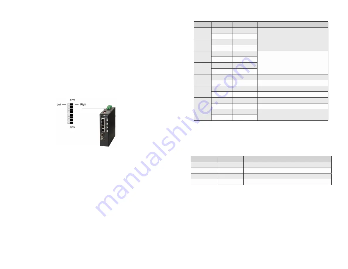
DIP-switches are located on the top of the module. The DIP-switches are used to
configure modes of operation and networking features.
DIP-switch Bank Locations
Page 6
The table below provides a description of each DIP-switch position and function.
Switch
Position
Legend
Function
SW1
LEFT
Single Switch
Mode of Operation
RIGHT
Dual Switch
SW2
LEFT
Switch
RIGHT
Directed Switch
SW3
LEFT
Off
Uplink Redundancy
RIGHT
Link Protection
SW4
LEFT
No Return
RIGHT
F1 Return
SW5
LEFT
MAC Learning
MAC Learning Enabled (factory default)
RIGHT
Off
MAC Learning Disabled
SW6
LEFT
Off
Pause Disabled (factory default)
RIGHT
Pause
Pause Enabled
SW7
LEFT
L2CP Tunnel
L2CP Tunnel (factory default)
RIGHT
Discard
L2CP Tunnel Discard
SW8
LEFT
OPT1 Off
Reserved
RIGHT
On
DIP-switch Definitions
SW1 and SW2: Mode of Operation
The module supports Switch, Directed Switch and Dual Device modes.
The modes are described with MAC learning enabled. When MAC learning is
disabled, unicast packets are forwarded to all ports.
SW1
SW2
Function
LEFT
LEFT
Switch Mode (factory default)
LEFT
RIGHT
Directed Switch Mode
RIGHT
LEFT
Dual Device Mode - Switch Mode
RIGHT
RIGHT
Dual Device Mode - Directed Switch Mode
Modes of Operation
Switch Mode
When configured for Switch Mode (factory default), the module operates as a
standard layer 2 switch. Data flow will follow MAC address mapping.
Directed Switch Mode
When configured for Directed Switch Mode, traffic from all the RJ-45 user ports (P1 -
P4 or P1 - P8) is only forwarded to the uplink port F1, preventing the broadcast traffic
from flooding other network ports. The data traffic on the additional uplink port (F2) is
also forwarded to port F1. Incoming traffic from F1 follows MAC address mapping.


