


17
AS7056/57 Advanced Automatic Offset Control (AAOC)
How to do the AAOC calibration
It is important to perform the AAOC calibration at
the beginning of the measurement in order to use
the AAOC function.
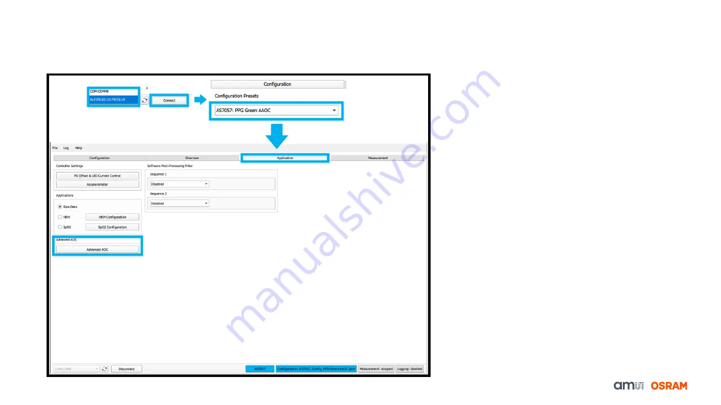
1.
After connecting, Select the right configuration
file from the provided configuration presets
(
AS7057: PPG Green AAOC
to use the AAOC
feature) in the configuration tab.
2.
Switch to the
“
Application
” Tab and press the
“
Advanced AOC
” to access the calibration
process.
Fig. 16: AAOC Calibration


