background image

27

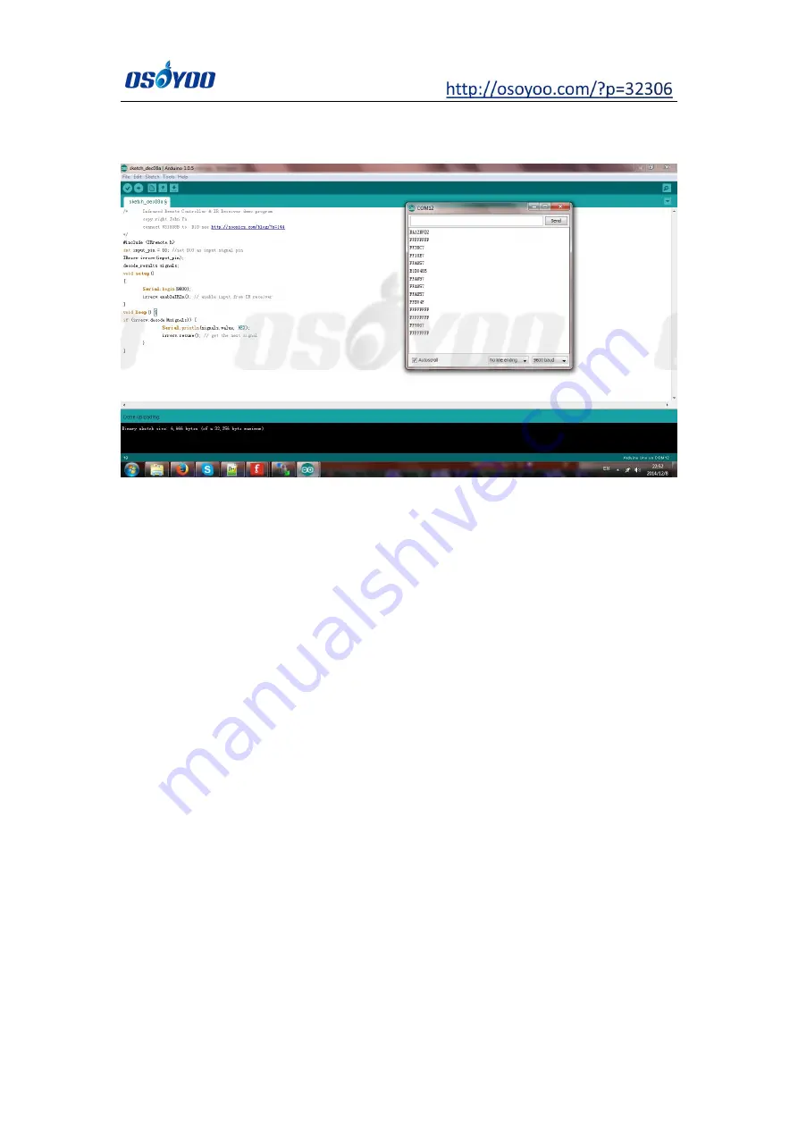
Press the “▲” “▼” “>” “<" "OK" button in your remote, you will see their IR code

as following picture:

Write down the IR code of your control buttons “▲” “▼” “>” “<” “OK” button.

Step B) Replace the IR code in lesson 2 sketch file:

Open your Lesson 2 code again, then you will see following lines define the IR

CODE of each button:

#define IR_ADVANCE 0x00FF18E7 //code from IR controller “▲” button

#define IR_BACK 0x00FF4AB5 //code from IR controller “▼” button

#define IR_RIGHT 0x00FF5AA5 //code from IR controller “>” button

#define IR_LEFT 0x00FF10EF //code from IR controller “<" button

#define IR_STOP 0x00FF38C7 //code from IR controller “OK” button

#define IR_turnsmallleft 0x00FFB04F //code from IR controller “#” button

Please change the value of each button in above lines to match the code

from Step A). If you don’t know how to change, just

send email to

[email protected]

and give us the code of each button from

Step A)

, I can

help you to change the code and email new sketch file to you.

Above method can also allow you to use other IR sending device (i.e TV

remote, DVD remote, air conditioner remote etc) to control the car. Just use

Step A)

to get the key code of your remote and change the sketch file in Step

B), it will work.

Summary of Contents for 3

Page 1: ...sting 26 Trouble shooting 26 Lesson 3 Line Tracking 28 Objective 28 Parts and Devices 28 Hardware Installation 29 Software Installation 31 Testing 34 Lesson 4 Don t Touch Me 35 Objective 35 Parts and Devices 35 Hardware Installation 36 Software Installation 41 Testing 44 Lesson 5 Obstacle Avoidance 45 Objective 45 Parts and Devices 45 Hardware Installation 46 Software Installation 47 Testing 49 Le...

Page 2: ...sembly instruction and video Even if you have no programming experience you can follow the step by step instruction and gradually become a master Our robotic car is 100 open source If you are an intermediate player and have time to read our code comments you can easily customize this robotic car to make your own project for science fair college home work or even commercial applications This kit co...

Page 3: ...ick here to buy 2 OSOYOO Motor Shield V1 0 1 Click here to buy 3 IR receiver 1 Click here to buy 4 Buzzer Sensor Module 1 Click here to buy 5 Tracking Sensor 1 Click here to buy 6 Ultrasonic Sensor 1 Click here to buy 7 Servo Motor 1 Click here to buy 8 Voltage Meter 1 Click here to buy ...

Page 4: ...ler 1 Click here to buy 11 Mount Holder for Ultrasonic Sensor 1 Click here to buy 12 Car Chassis 1 Click here to buy 13 Motor with wires 1 Click here to buy 14 Wheels 2 Click here to buy 15 Universal Wheel 1 Click here to buy 16 9V Battery Box 1 Click here to buy ...

Page 5: ...Click here to buy 19 Hex Screwdriver 1 Click here to buy 20 20pin 15cm Female to Female Cable 1 Click here to buy 21 7pin 25cm Female to Female Cable 1 Click here to buy 22 3pin 15cm Female to Female Cable 1 Click here to buy 23 Rubberized Tape 1 Click here to buy ...

Page 6: ...6 ...

Page 7: ...d program the car to do some simple movements If you have passed the test movement of this lesson it means Arduino motor control module motors batteries chassis and wire connections between these parts are all functioning well As your experiments in future lessons are all based on the frame work of Lesson 1 it is very important to test the installation and sample code in this Lesson properly Parts...

Page 8: ... with Arduino UNO R3 1 Click here to buy 2 OSOYOO Motor Shield V1 0 1 Click here to buy 3 Voltage Meter 1 Click here to buy 4 Car Chassis 1 Click here to buy 5 Motor with wires 1 Click here to buy 6 Wheels 2 Click here to buy 7 Universal Wheel 1 Click here to buy ...

Page 9: ...assis 8 9V Battery Box 1 Click here to buy 9 9V Battery 1 Click here to buy 10 Phillips Screwdriver 1 Click here to buy 11 Hex Screwdriver 1 Click here to buy 12 20pin 15cm Female to Female Cable 1 Click here to buy 13 3pin 15cm Female to Female Cable 1 Click here to buy ...

Page 10: ...10 Step 2 Install the motor under the chassis with M3 Hex screws and nuts as follow Step 3 Install the universal wheel with the M3 Hex screws and copper pillars ...

Page 11: ... universal wheel under the chassis with the M3 Hex screws Step 5 Install OSOYOO UNO Board on the chassis with M3 plastic screws pillars and nuts Step 6 Install the battery box on the chassis with M3 Phillips screws and nuts ...

Page 12: ...12 Step 7 Plug the OSOYOO Motor Shield V1 0 Board in OSOYOO UNO board Step 8 Install the voltage meter on the chassis with M3 plastic screws pillars and nuts ...

Page 13: ...13 Connection Step 1 Connect OSOYOO Motor Shield V1 0 with the motor ...

Page 14: ...OSOYOO Motor Shield V1 0 please refer to this link https osoyoo com 2020 08 06 osoyoo motor shield Step 2 Connect OSOYOO Motor Shield V1 0 with the battery box Step 3 Connect OSOYOO Motor Shield V1 0 with the voltage meter ...

Page 15: ...est Arduino IDE If you have Arduino IDE version after 1 1 16 please skip this step Download Arduino IDE from the follow link then install the software https www arduino cc en Main Software setlang en Open source Arduino Software IDE Download Arduino IDE here https www arduino cc en Main Software setla ng en 7 zip is a free zip utility that un zips zip files Download 7zip here for free https www 7 ...

Page 16: ...son 1 zip and unzip it you will see a folder called lesson 1 Step3 Connect UNO R3 board to PC with USB cable open Arduino IDE choose corresponding board port for your project Notice Shut off your battery or Unplug your power adapter when upload sketch code to Arduino ...

Page 17: ...17 Step 4 Click file click Open choose code lesson 1 ino load the code into Arduino and then upload the sketch to the board ...

Page 18: ...18 ...

Page 19: ...ct otherwise it can destroy your device and cause fire hazard Put the car on the ground turn on the switch of OSOYOO Motor Shield V1 0 the car should go forward then go backward then left turn then right turn then stop If the car does not move as per above mentioned result you should check your wire connection 7 jumper caps on OSOYOO Motor Shield V1 0 battery voltage must over 7 2v ...

Page 20: ...soyoo Model 3 Robot Learning Kit to make a simple remote controlled smart car Once the car installation is completed we will use an Infrared Remote to control the car movements including go forward go back left turn and right turn Parts and Devices No Device Picture Qty Link ...

Page 21: ...ck here to buy 3 Hex Screwdriver 1 Click here to buy 4 20pin 15cm Female to F emale Cable 1 Click here to buy Hardware Installation Step 1 Install the smart car basic frame work as per Lesson 1 If you have already completed installation in Lesson 1 just keep it as is ...

Page 22: ...eceiver module with 2pcs M3 plastic screws M3 plastic pillars and M3 plastic nuts as follow Step 3 Connect S VCC GND or the IR Receiver with D12 5V GND of OSOYOO Motor Shield V1 0 as the following photo Remember DO NOT remove any existing wires installed in Lesson 1 ...

Page 23: ... Download 7zip here for free https www 7 zip org Step 1 Install latest Arduino IDE If you have Arduino IDE version after 1 1 16 please skip this step Download Arduino IDE from the follow link then install the software https www arduino cc en Main Software setlang en Step 2 Install IRremote library into Arduino IDE If you have already installed IRremote library please skip this step ...

Page 24: ...p 3 Download https osoyoo com picture 2WD_Car_V2 0 code lesson2 zip and unzip the download zip file lesson2 zip you will see a folder called lesson2 Step 4 Connect UNO R3 board to PC with USB cable Open Arduino IDE click file click Open choose code lesson2 ino in lesson2 folder load the code into arduino Notice Shut off your battery or Unplug your power adapter when upload sketch code to Arduino ...

Page 25: ...25 Step 5 Choose corresponding board and port for your project upload the sketch to the board ...

Page 26: ...te sends different button code which does not match our sample code In order to solve this problem Please take following steps Step A Get the IR code of each button in your IR remote Copy code from following link https osoyoo com wp content uploads samplecode irdemo2 ino Upload above sketch into your Arduino and open the serial monitor in your upper right corner ...

Page 27: ..._LEFT 0x00FF10EF code from IR controller button define IR_STOP 0x00FF38C7 code from IR controller OK button define IR_turnsmallleft 0x00FFB04F code from IR controller button Please change the value of each button in above lines to match the code from Step A If you don t know how to change just send email to support osoyoo info and give us the code of each button from Step A I can help you to chang...

Page 28: ...mework built in Lesson 1 If you have not completed installation in Lesson 1 please review Lesson 1 The software in this lesson will read data from the tracking sensors and automatically guide the car to move along the black track line in the white ground Parts and Devices No Device Picture Qty Link ...

Page 29: ...m previous status of Lesson 1 If you have installed Lesson 2 no need change anything just keep the hardware wire connection as is 1 Tracking Sensor 1 Click here to buy 2 Hex Screwdriver 1 Click here to buy 3 7pin 25cm Female to Female Cable 1 Click here to buy ...

Page 30: ...opper pillars and M3 nuts as following Step 3 Connect GND VCC pin of tracking sensor module to GND 5V of OSOYOO motor shield V1 0 connect IR1 IR2 IR3 IR4 IR5 pins to A0 A1 A2 A3 A4 with 7pin 25cm female to female cable as the following photo shows Remember DO NOT remove any existing wires installed in Lesson 1 ...

Page 31: ...www arduino cc en Main Software setlang en Step 2 Download http osoyoo com picture V2 0_Model_3_Robot code lesson3 zip unzip the download zip file lesson3 zip you will see a folder called lesson3 Open source Arduino Software IDE Download Arduino IDE here https www arduino cc en Main Software setla ng en 7zip is a free zip utility that un zips zip files Download 7zip here for free https www 7 zip o...

Page 32: ...click file click Open choose code lesson3 ino in lesson3 folder load the code into arduino Notice Shut off your battery or Unplug your power adapter when upload sketch code to Arduino Step 4 Choose corresponding board port for your project upload the sketch to the board ...

Page 33: ...old the car and adjust the potentiometer on the tracking sensor with cross screwdriver until you get the best sensitivity status the signal indicate LED light will turn off when sensor is above white ground and the signal LED will turn on when the sensor is above black track ...

Page 34: ...s than 30mm in white ground Please note the bend angle of track can t be larger than 90 degree If the angle is too large the car will move out of the track Turn on the car and put the middle of tracking sensor module facing over black track and then the car will move along the black track ...

Page 35: ... an ultrasonic sensor on the robot car and program the car to keep some distance of object to move You must complete Lesson 1 assembling the car before you continue on with this lesson Parts and Devices No Device Picture Qty Link 1 Ultrosonic Sensor 1 Click here to buy ...

Page 36: ...1 Click here to buy 4 Buzzer Sensor Module 1 Click here to buy 5 20pin 15cm Female to Female Cable 1 Click here to buy Hardware Installation Step 1 Install the smart car basic frame work as per Lesson 1 If you have already completed installation in Lesson 1 just keep it as is ...

Page 37: ...of car chassis with 2pcs M2 2 8 Self Tapping Screws as following Step 3 Install ultrasonic module to mount holder with 4pcs M1 5 8 screw and M1 5 nuts Step 4 Install mount holder for Ultrasonic Module on servo motor with M2 4 Self Tapping Screw ...

Page 38: ...module on car chassis with 1pc M3 plastic screw M3 plastic pillar and M3 plastic nut Step 6 Connect SG90 servo motor to OSOYOO motor shield V1 0 as following graph Remember DO NOT remove any existing wires installed in Lesson 1 ...

Page 39: ...39 Step 7 Connect ultrasonic module with OSOYOO motor shield V1 0 as below connection diagram ...

Page 40: ...40 Step 8 Connect buzzer module with OSOYOO motor shield V1 0 as below connection diagram ...

Page 41: ...tallation Open source Arduino Software IDE Download Arduino IDE here https www arduino cc en Main Software setla ng en 7zip is a free zip utility that un zips zip files Download 7zip here for free https www 7 zip org ...

Page 42: ...om picture 2WD_Car_V2 0 code lesson4 zip unzip the download zip file lesson4 zip you will see a folder called lesson4 Step 3 Connect Arduino UNO to PC with USB cable Open Arduino IDE click file click Open choose code lesson4 ino in lesson4 folder load the code into arduino Notice Shut off your battery or Unplug your power adapter when upload sketch code to Arduino Step 4 Choose corresponding board...

Page 43: ...straight forward If it is not straight forward you should turn off the car immediately and remove the sensor from servo reinstall it and make it facing straight forward direction as following picture Otherwise the obstacle avoidance program will not work properly After adjusting sensor direction power on the car again After hearing the long beep the sensor should face front same as following pictu...

Page 44: ...and before ultrasonic module and then the car will move in some distance of object or your hand when you close the car the car will move back just as it says don t touch me when object or your hand leave the ultrasonic module the car will stop moving ...

Page 45: ...ith this lesson we use the ultrasonic module to see obstacle and measure the distance If the distance is less than predefined threshold value the buzzer will beep and the car will turn around from the obstacle automatically Parts and Devices No Device Picture Qty Link 1 Ultrosonic Sensor 1 Click here to buy ...

Page 46: ...or 1 Click here to buy 4 Buzzer Sensor Module 1 Click here to buy 5 20pin 15cm Female to Female Cable 1 Click here to buy Hardware Installation Install the smart car basic frame work as per Lesson 4 If you have already completed installation in Lesson 4 just keep it as is ...

Page 47: ...load zip file lesson5 zip you will see a folder called lesson5 Step 3 Connect Arduino UNO to PC with USB cable Open Arduino IDE click file click Open choose code lesson5 ino in lesson5 folder load the code into arduino Notice Shut off your battery or Unplug your power adapter when upload sketch code to Arduino Open source Arduino Software IDE Download Arduino IDE here https www arduino cc en Main ...

Page 48: ...48 Step 4 Choose corresponding board port for your project upload the sketch to the board ...

Page 49: ...diately and remove the sensor from servo reinstall it and make it facing straight forward direction as following picture Otherwise the obstacle avoidance program will not work properly After adjusting sensor direction power on the car again After hearing the long beep the sensor should face front same as following picture If its direction is not straight forward turn off the car and do direction a...

Page 50: ...ounding obstacle The robot car will decide to make left turn right turn or backward according to obstacle sensor data and our obstacle avoidance algorithm Sometimes your car might have collision and make your Ultrasonic sensor position change you must remember to do sensor direction alignment again as Step 5 Ultrasonic sensor servo initial direction alignment ...

Page 51: ...and make an imitation driving Since is a mock driving we will use a virtual steering wheel and gear in our APP to imitate their counterparts in real car You must complete Lesson 1 assembling the car before you continue on with this lesson Parts and Devices No Device Picture Qty Link 1 HC module 1 Click here to buy ...

Page 52: ... frame work as per Lesson 1 If you have already completed installation in Lesson 1 just keep it as is Step 2 Insert Bluetooth Module into OSOYOO motor shield V1 0 Bluetooth slot as following graph Remember DO NOT remove any existing wires installed in Lesson 1 ...

Page 53: ...ain Software setla ng en 7 zip is a free zip utility that un zips zip files Download 7zip here for free https www 7 zip org OSOYOO imitation driving Robot APP Search OSOYOO imitation driving in Google Play or Apple APP store Step 1 Install latest Arduino IDE If you have Arduino IDE version after 1 1 16 please ...

Page 54: ...ad zip file lesson6 zip you will see a folder called lesson6 Step 3 Connect Arduino UNO to PC with USB cable Open Arduino IDE click file click Open choose code lesson4 ino in lesson4 folder load the code into arduino Notice Remove the bluetooth module and Shut off your battery or Unplug your power adapter when upload sketch code to Arduino Step 4 Choose corresponding board port for your project up...

Page 55: ...Google Play store search APP name OSOYOO imitation driving download the APP as following and install it in your smart phone If you can not use Google Play to find the APP please Download the APP from following link https osoyoo com driver v1car apk 2 Install APP on Apple IOS device as following ...

Page 56: ...and install it in your smart phone Explanation of APP UI UI is different between Android and IOS BT Search button When click this button you will see a Bluetooth device list which has been paired with your APP Select HC 02 device to connect the car Once HC 02 is connected Bluetooth Status will ...

Page 57: ...oggle Engine button again to enable other button On the other hand when F5 is clicked the car will stop but all other buttons is still active Even you do not touch any button just change your cell phone angle position like you move the steering wheel the car will move again Direction Steering Wheel When you rotate your mobile phone angle the steering wheel will change angle as per your mobile phon...

Page 58: ... Setting Bluetooth setting and search a Bluetooth device called HC 02 pair it with code 1234 Step 3 Open OSOYOO imitation driving Robot APP Click BT Search button and find the bluetooth you have paired Step 4 Turn on Engine toggle click Speed to make the robot speed up as the robot car is very slow at first And When you rotate your mobile phone angle your car will change direction Enjoy your drivi...

Reviews: