background image


OPERATION


Control mode

1. Control panel

2. Infrared remote 

control

3. Computer. Each of them can be carried out 

separately or combined. 

1.

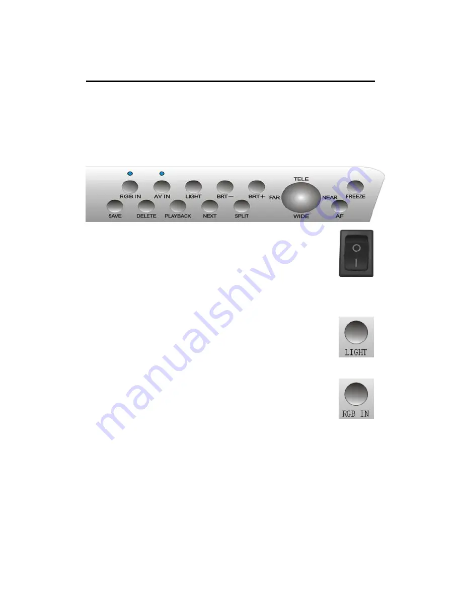
 CONTROL PANEL


POWER:


Switch the button to “

”, the indicator lights of 

“RGB” and “AV” will twinkle to green. It means 

“Power on”. 

Switch the button to ”

” to shut off. 


7

LIGHT: 

Press “Light” to on/off the upperlight or 

baselight. 

RGB IN


Repeatedly pressing “RGB switch” to select 

machine signal and external PC RGB signal input. 
When choosing machine RGB signal, ”RGB switch” indicator 
light would comes green continually, when choosing external 
PC RGB1 signal, ”RGB switch” indicator light would comes 
orange continually, when choosing PC RGB2 signal, ”RGB 
switch” indicator light would comes red continually. Note: If 
current state was VGA signal output, there is no AV signal 
outputed . 

Summary of Contents for PH-9500S

Page 1: ...MULTI MEDIA HIGH RESOLUTION DIGITAL PRESENTER Operation Manual Please read this manual carefully before operation ...

Page 2: ...e cables with power on 3 Do not try to change the structure Do not operate when it is naked 4 Keep this instrument from tinderbox liquid or metal Do not present tinderbox or liquid on the base board 5 Do not use this instrument under situations like high temperature wet caustic gases dusty or shaky Please place it on STABLE desk Objects should be less than 1kg 6 Remove power supply before cleaning...

Page 3: ... shaking problems when displaying small characters It can be connected with a projector or displayed directly through RGB ports which is especially suitable for teaching and presentation With ESD static protection function it protects the components when switching plug electriferously Strong image processing ability Freeze Division Color B W Negative Mirror Image save Brightness etc Several inputs...

Page 4: ... BASIC INTRODUCTION 2 STRUCTURE PARTS 4 STRUCTURE 4 BACK 4 CONNECTION 5 BASIC OPERATION 6 SET UP 6 FOLD 6 OPERATION 7 CONTROL PANEL 7 REMOTE CONTROL 11 COMPUTER 15 DAILY MAINTANCE 16 F A 17 SPECIFICATIONS 18 ACCESSORIES 19 3 ...

Page 5: ...ole 4 Main pole lock 5 Power switch 6 Camera head 7 Infrared port 8 Camera 9 Upper light 10 Upper light arm 11 Base light 12 Control panel 13 Microphone plug volume 1 2 9 10 11 12 7 8 3 9 10 BACK 1 2 4 5 6 3 2 7 1 RGB In 2 RGB Out 3 RS 232 4 USB optional 5 AV Input 6 AV Output 7 Input port of direct current 12V 1 5A 13 6 4 5 ...

Page 6: ... CONNECTION CONNECTION Computer Lap top VCD DVD VCR LCD Projector TV Back shoot Digital TV Notes Please disconnect the visual presenter when under assembling 5 ...

Page 7: ...p the upper light arms and adjust the direction Notes Do not press the Flexible role button when raise the flexible role 7 6 5 3 4 2 2 1 FOLD 1 Make the upperlight arms vertically parallel Lay down the arms 3 4 Press the Flexible pole button and lay down the flexible pole 5 Make the camera head vertically parallel to the main pole 6 7 Press the main pole button and lay down the pole 6 ...

Page 8: ... Press Light to on off the upperlight or baselight RGB IN Repeatedly pressing RGB switch to select machine signal and external PC RGB signal input When choosing machine RGB signal RGB switch indicator light would comes green continually when choosing external PC RGB1 signal RGB switch indicator light would comes orange continually when choosing PC RGB2 signal RGB switch indicator light would comes...

Page 9: ...nge continually when choosing external AV signal 2 AV switch indicator light would comes red continually Note If current state is AV signal output there is no VGA signal outputed TELE WIDE Press the TELE WIDE button to zoom in out the image AF FAR NEAR Press AF button for auto focus press Tele or WIDE button to adjust focus gradually and constantly Press this button for 3 seconds to enter into the...

Page 10: ...ith BRT BRT FREEZE Press FREEZE to freeze the current image for detailed studying re press it to cancel DELETE Under the state of Preview to press Delete OSD shows Delete then press Delete again to confirm deleting this image press other keys to quit 9 ...

Page 11: ...L1 2 NEXT In the state of Preview press Next to preview circularly and press Next to save or delete images by choosing ID SAVE Press Save to save the current image to the imag saving chip Note When images are full and there are more to be saved the previous images would be covered Also images could be saved to the designated position Do it as followed Before savimg press the Next on the remote con...

Page 12: ...VOL Increase volume VOL Reduce volume AV Switch the AV signal output to the TV RGB Switch the RGB signal output to the projector or PJTV SIGNAL RGB and AV signal output switch DIVISION Freeze the left part of image move and compare with right part of image ROTATE W B Color of image FREEZE Freeze the shooting image NEGATIVE Show image in positive negetive form TEXT Display picture in text image for...

Page 13: ...K Display stored image fulfilled screen DELETE Delete choosed picture in splited state TELE Enlarge image WIDE Contract image AF Focus automatically one time FAR Focus manually NEAR Focus manually OPERATION 12 ...

Page 14: ...up After entering into the menu press WIDW or TELE to select the option to be set up and then press Far or Near to set up the detailed specification under each option Press Tele Wide to come to the image setting selection press Focus to come to operation press Tele Wide to select operation items needed press Far Near to setup the selected items After entering the image setting which could setup th...

Page 15: ...elect the mode of beforehand default color or select the user defined mode then come to the adjustment of R OFFSET G OFFEST and B OFFEST After entering to the system setting item which could select the language Pal NTSC and default setting could be choosed offered by TV mode 14 ...

Page 16: ...ter with computer with the attached RS 232 cable Please insert the attached disk into the computer driver under Windows 9X 2K XP Follow the instructions to complete the installation Then run C Program Files Video presenter software PRESENTER EXE or click the PRESENTER icon on the desktop you will enter the Software interface as shown 15 ...

Page 17: ...ent Do not move it by lifting the main pole or light arm 5 Do not bend the arms up to 90 neither revolve it horizontally 6 Do not try to pull out the flexible arm when the equipment is folded 7 Do not push hard when lying down the light arms 8 Keep this equipment dry Do not try to wipe the camera with fingers 9 Please release the power cable when unused and cover it with cloth 10 The validity peri...

Page 18: ...ean it Image confusing It s because when zoom in in a dark situation there will be confusion of the image Please turn on the upper light Maybe it is because of the shortness of light Turn on the upper light Image is too dark Or reset the brightness Control panel unworkable Do not switch the buttons too speedily Take a stop before pressing the next button Make sure nothing is stocked between the re...

Page 19: ... inside outside and Manual white balance red blue Video Image processing Color B W Positive Negative Mirror Brightness Freeze Compare Upperlight 1 5W LED 2 or Tricolor T4 6W 2 Rlight Baselight CCFL cold cathode baselight 6W AV Host outer AV signals switch Input RGB Host outer RGB signals switch RGB D SUB15 pin plug Multiple Video RCA plug 1V 0 2Vp p 75Ω Audio stereo RCA plug 10dB 10KΩ S Video Mini...

Page 20: ...er 16W Environment Tempreture 0 40 Set up 450 370 270 410 mm Dimension W D H Folded 450 370 150 mm Optional USB Note Specifications are subjected to change without notice Accessories Item Unit QTY User manual PCS 1 Remote controller PCS 1 Control software CD PCS 1 Power adapter PCS 1 USB cable PCS 1 RGB cable PCS 1 RS 232 cable PCS 1 AV cable PCS 1 S video cable PCS 1 Warranty card PCS 1 Note It i...

Reviews: