SECTION 3 - CHASSIS & TURNTABLE
3-42
– JLG Lift –
3121827
IF COMPRESSED AIR OR ELECTRICALLY OPERATED IMPACT
WRENCH IS USED FOR TIGHTENING THE BEARING ATTACHMENT
BOLTS, THE TORQUE SETTING ACCURACY OF THE TOOL SHOULD
BE CHECKED PRIOR TO USE.
g.
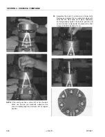
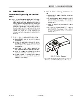
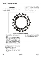
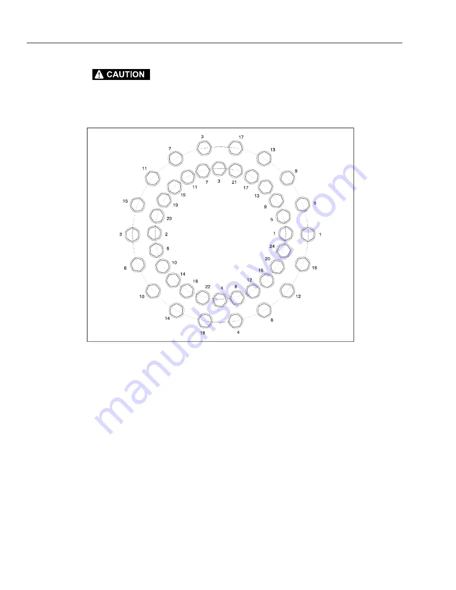
Following the torque sequence diagram shown
in Figure 3-15., tighten the bolts to an initial
torque of 130 ft. lbs. (175 Nm). Then following
the same sequence, tighten to a final torque of
190 ft. lbs. (260 Nm).
h.
Remove lifting equipment from bearing.
i.
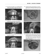
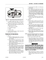
Use suitable lifting equipment to carefully posi-
tion the turntable assembly above the machine
frame.
j.
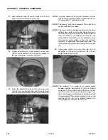
Carefully lower the turntable onto the swing
bearing. Ensure that the scribed line of the inner
race of the bearing aligns with the scribed mark
on the turntable. If a new swing bearing is used,
ensure that the filler plug fitting is at 90 degrees
from the fore and aft centerline of the turntable.
k.
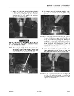
Apply a light coating of Loctite 271 to the new
bearing bolts and install through the turntable
and inner race of bearing.
3.
Following the torque sequence shown in Figure 3-
15., tighten the bolts to an initial torque of 130 ft. lbs.
(175 Nm). Then following the same sequence,
tighten the bolts to 190 ft. lbs (260 Nm).
a.
Remove the lifting equipment.
b.
Route hydraulic lines through center of turntable
and frame and connect as tagged prior to
removal.
c.
Using all applicable safety precautions, activate
the hydraulic system and functionally check
swing system for proper and safe operation.
Figure 3-15. Swing Bearing Torquing Sequence
Summary of Contents for JLG E400AJP
Page 2: ......
Page 32: ...SECTION 1 SPECIFICATIONS 1 18 JLG Lift 3121827 NOTES...
Page 42: ...SECTION 2 GENERAL 2 10 JLG Lift 3121827 NOTES...
Page 54: ...SECTION 3 CHASSIS TURNTABLE 3 12 JLG Lift 3121827 Figure 3 3 Speed Sensor Orientation...
Page 60: ...SECTION 3 CHASSIS TURNTABLE 3 18 JLG Lift 3121827 Figure 3 7 Steering Components and Spindles...
Page 62: ...SECTION 3 CHASSIS TURNTABLE 3 20 JLG Lift 3121827 Figure 3 9 Tilt Sensor Location...
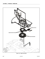
Page 86: ...SECTION 3 CHASSIS TURNTABLE 3 44 JLG Lift 3121827 Figure 3 16 Swing Components...
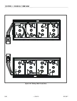
Page 88: ...SECTION 3 CHASSIS TURNTABLE 3 46 JLG Lift 3121827 Figure 3 18 Battery Cable Connections...
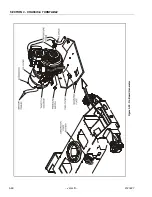
Page 90: ...SECTION 3 CHASSIS TURNTABLE 3 48 JLG Lift 3121827 Figure 3 20 On Board Generator...
Page 97: ...SECTION 3 CHASSIS TURNTABLE 3121827 JLG Lift 3 55 Figure 3 22 Generator Components...
Page 116: ...SECTION 3 CHASSIS TURNTABLE 3 74 JLG Lift 3121827 NOTES...
Page 127: ...SECTION 4 BOOM PLATFORM 3121827 JLG Lift 4 11 Figure 4 10 Boom Limit Switches...
Page 140: ...SECTION 4 BOOM PLATFORM 4 24 JLG Lift 3121827 Figure 4 13 Rotator Counterbalance Valve...
Page 178: ...SECTION 5 HYDRAULICS 5 24 JLG Lift 3121827 Figure 5 26 HydraForce Cartridge Torque Value Chart...
Page 214: ...SECTION 6 JLG CONTROL SYSTEM 6 34 JLG Lift 3121827 NOTES...
Page 257: ......

