Operating manual Pool-Master 400 Page: 2
Electrical connection:
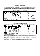
The electrical connection, and adjustment work and service may only be carried out by an
approved electrician! The following terminal diagram and the currently applicable safety
regulations must be observed.
When using a 400V three-phase current pump:
When using a 230V alternating current pump:
This control is not suitable for the connection of a filter pump with speed control. For such pumps we have
other controls in our product range
The bridge between the two terminals labelled
WSK
inserted at the factory must be removed when connecting
a motor winding protection contact. If no connection is made, it must be left screwed in place.
A
floating contact
for connecting the feeder is provided at terminals
D/D
. This contact is always closed when
the filter pump is operating.
A 2A fine-wire fuse in the terminal box protects the electronic control together with the heating.
NTC
water
temp.
sensor
Pool Master 400
Filter pump
400V
max. 8A
D
o
s
ing
c
o
n
tr
o
l
floa
ting
c
o
n
ta
c
t
max
.
8
A
L1 L2 L3 N
Mains
3/N/PE
400V 50Hz
15 16
U1
W1
V1
WSK Th Th U2 N
D D
h
e
a
te
r
max
4
0
0
W
M
3~
w
ind
ing
p
ro
te
c
tion
c
o
n
ta
c
t
s
a
fe
ty
te
mpe
ra
tu
re
limi
te
r
motor protection
NTC
water
temp.
sensor
Pool Master 400
Filter pump
230V
max. 8A
D
o
s
ing
c
o
n
tr
o
l
floa
ting
c
o
n
ta
c
t
max
.
8
A
L1 L2 L3 N
Mains
1/N/PE
230V 50Hz
15 16
U1
W1
V1
WSK Th Th U2 N
D D
h
e
a
te
r
max
4
0
0
W
M
1~
w
ind
ing
p
ro
te
c
tion
c
o
n
ta
c
t
s
a
fe
ty
te
mpe
ra
tu
re
lim
it
e
r
motor protection


