
Installation Instructions for VAPRO Rupture Disks in VRDI
Holder
P.O. Box 1327 / 1701 W. Tacoma/ Broken Arrow, OK 74012
Telephone: (918) 258-5626 Fax: (918) 251-2809
“Quality Products to meet Industry Needs”
PS 11.12
RUPTURE DISK INSTALLATION
1)
Carefully unpack the rupture disk from its box. If
your disk assembly was packaged with a dome-shaped
shipping protector marked
"SHIPPING PROTECTOR -
DO NOT USE"
, remove it now.
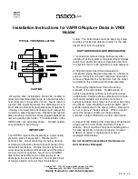
2)
Place the Insert VRDI Inlet on flat work surface
with the knife blades pointing up. Place the rupture disk
assembly on the holder, carefully aligning the holes in
the flange portion of the rupture disk assembly with the
alignment pins in the VRDI inlet.
3)
Position the Insert VRDI Outlet over the dome of
the rupture disk assembly, carefully aligning the VRDI
Inlet alignment pins with the holes in the VRDI Outlet.
Lower the VRDI Outlet until it engages the VRDI Inlet
alignment pins and rests on the flat outer annular seating
surface of the rupture disk assembly. No binding should
occur during this procedure. If interference occurs,
discontinue installation until the source of the
interference is determined and corrected.
4)
Install side bars; however, cap screws should
only be snug,
not
wrench tight.
5)
Check companion flanges and verify that sealing
surfaces are clean, free of corrosion and debris, and are
not bent or warped.
6)
Position the Vapro/VRDI assembly within the bolt
circle of companion piping flanges. The concave side of
the rupture disk assembly should face the process or
possible vacuum source. Reinstall studs, nuts and
suitable gaskets. Studs and nuts should be lightly oiled
and free running.
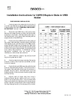
7)
Tighten each nut finger tight, then using a
calibrated torque wrench, tighten each nut in a cross
pattern. Use increments of 20% of the recommended
torque value listed in the table below. Do not use torque
values in excess of those shown in the Torque Table as
this may damage the disk or the bite seal on the holder.
VAPRO / VRDI TORQUE TABLE
SIZE
FLANGE
RATING
RECOMMENDED
TORQUE VALUE
IN.
mm
ANSI
DIN
Ft-Lb
N-M
3
80
150
-
40
54
-
-
-
10/16
20
27
4
100
150
10/16
30
41
6
150
150
-
40
54
-
-
-
10/16
42
57
8
200
150
-
50
68
-
-
-
10
52
70
-
-
-
16
35
47
10
250
150
-
70
95
-
-
-
10
63
85
-
-
-
16
76
103
12
300
150
-
80
108
-
-
-
10
72
98
-
-
-
16
86
117