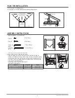

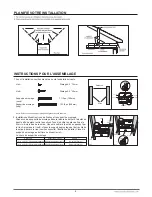


3. Mount with hanger bars only
Slide hanger bars onto housing and adjust as needed to fit between
framing. Extend the hanger bars to the width of the framing. Position the
ventilator with the hanger bar tabs wrapped around the bottom edge of
the framing, holding the ventilator in place.
Secure hanger bars to framing using one screw on each end of hanger
bar. (refer to the right diagram)
Screw hanger bar to housing with screw A.
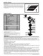
4. Mount to I-joist
Slide one hanger bar (long) into channel B on the housing and adjust as
needed to fit between framing. Hold housing in place so that the housing
contacts the bottom of the joist
.
Screw housing to joist through the hole D
and hole C. Screw the hanger bar onto the other side of joist through the
hole (refer to the right diagram).
Screw hanger bar to housing with screw A.
5. INSTALL ROUND DUCTWORK
Connect the round ductwork (not included) to the damper/duct connector,
and run the ductwork to a roof or wall cap (not included). Using tape (not
included), secure all the ductwork connections so that they are air tight.
Run 120 V AC house wiring to the location of the fan. Use only UL-approved connectors (not included) to attach the house wiring to the
wiring plate. Refer to the wiring diagram, and connect the wires as shown.
ASSEMBLY INSTRUCTIONS
CONNECT ELECTRICAL WIRING
3
Distance A
14 in to 23 1/2 in (356mm-597mm)
21 1/4 in to 23 1/2 in (540mm-597mm)
Hanger Bar A
Hanger bar (short)
Hanger bar (long)
The choice of Hanger Bar A
Hanger bar (long)
Hanger bar A
Screw A
Screw B
Screw A
Screw A
Screw B
UNIT
BLACK (BLK)
SWITCH BOX
POWER SUPPLY
120V AC
GROUND (GRD)
WHITE (WHT)
FAN
RECEPTACLE
FAN
WIRE
PANEL
BLK
BLU
BLK
SWITCH
SWITCH
BLUE (BLU)


