36
Gas
The fireplaces are approved for use with natural gas (NG) or propane (LP) only. No other fuel types are permitted.
Gas Pressures
Fireplace Series
Burner
Gas Type
Inlet Pressure Manifold
Pressure
Heat Input
(BTU/hr)
Orifice
Size
Min
Max
Min
Max
77HH Front
77HH RS
77HH LS
77HH TS
160 Single
Burner
Natural Gas
7.0
11.0
4.5
27,467 51,277
1400
Propane
11.0
13.0
10.0
24,329 51,011
500
NOTE: It can take up to 20 minutes for the flames to turn yellow.
Routing the Gas Line
Correctly size and route the gas supply line from the supply regulator to the area where the access panel is located (or to the burner
area if no access panel is available), as per the requirements outlined in the latest edition of the National Fuel Gas Code, NFPA 54
(USA) or CAN/CSA-B1491 (Canada).
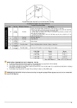
The gas and electrical components are attached to the pilot on a flexible gas line and can be kept directly under the fireplace
or, depending on the model, moved to the left, right, or back of the fireplace within 36 inches of the pilot (located at the
center front of the burner). See images below for details.
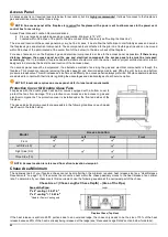
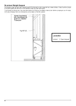
Gas line should be routed to the access panel area (see “Access Panel” section on page 22 for details). If no access panel is planned,
gas line should be routed to the most accessible area within the 36” radius.
A gas shut-off valve and a 12” gas flex connector are provided with every fireplace. The location of the gas shut-off valve is dependent
on local codes and requirements. Check with your authority having jurisdiction for more information.
WARNING: The main gas valve must be installed to allow complete disconnection of the fireplace from the gas supply
piping system for servicing purposes.
Front Model: Left, Right, Back
Three Sided Model: Back
Right Side (RS) Model: Left, Back
Left Side (LS) Model: Right, Back

