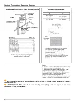
ORTAL 77HH Corner LS Installation And Operation Manual Download Page 22

22 

Access Panel 

An access panel is not required (see note below for exception), but it is 

highly recommended

. It allows for access to the fireplace’s 

gas and electrical components for servicing.  

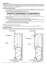
 NOTE: An access panel at the fireplace is 

required

 for fireplaces with a power vent to allow access to the power vent 

control box for servicing. 

Access Panel Size and Location Recommendations: 

  Size: as large as possible depending on application. Minimum is 10”x10”. 

  Located within 36 inches of the pilot to the side or back of the fireplace (see “Routing the Gas Line”) 

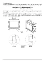
The size and location of the access panel may vary, but in all cases, it must allow the technician to comfortably access and service 

the fireplace’s gas and electrical components. These components are attached to the pilot on a flexible gas line and can be moved 

within 36 inches of the pilot (located at the center front of the burner) to the side or back of the fireplace. 
For ease of access, move the fireplace’s gas and electrical components as close to the access panel as possible

. If there is any 

distance between the access panel and the gas and electrical components, the access panel size must be increased 

accordingly.

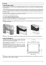
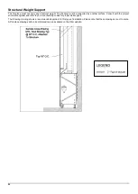
 Prior to installation, fireplace dealers/installers should work with the owner, builder, project architects and/or interior 

designers to determine the best size and location of their access panel. 
If an access panel cannot be incorporated, the alternative method of servicing the gas and electrical components is though the 

fireplace. This procedure requires removing the glass panel(s) and interior design media, and lifting the grill, burner, and bottom 

pressure release valve. This will increase service time and difficulty. An access panel is always preferred. Fireplace dealers/installers 

are advised to consult with their clients regarding the advantages and disadvantages of each service option. 


NOTE: If local code requires an access panel, defer to local code requirements.


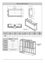
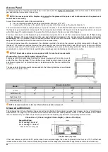
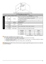
Protective Cover for Double Glass Fans 

Fireplaces with the double glass heat barrier comes equipped with a bottom cover to 

protect the fans from damage. This protective cover blocks service access to gas and 

electrical components. The protective cover is installed under the front and sides of the 

fireplace.  
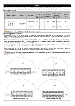
The gas and electrical components are accessible in the following locations on each model 

(as shown in the table below). 


Model 

Access Location 

Right 

Left 

Back 

Front 

Front 


Left Side (LS) 


Right Side (RS) 


Three Side (TS) 


 NOTE: Access location is referenced from a front elevation viewpoint. 
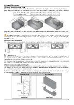
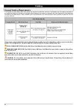
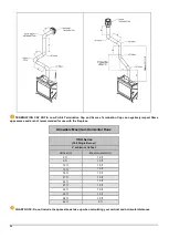
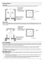
Chase Area Minimum 

The narrowest part of your fireplace chase cannot be smaller than the minimum required heat release size (see “Heat Release 

Requirements” on page 16). This ensures the convective heat within the chase passively moves to the heat release at an optimal 

rate. To determine if your chase meets this requirement, use the following equation at the narrowest part of the chase. 

Chase Area = (Chase Length x Chase Depth) – (Area of the Pipe)


Area of the Pipe: 

5”x8” venting = 50.27 in

2


3”x5” venting

*

 = 19.63 in

2


*Used for Power Venting only


Fireplace Chase (Top View) 


If the heat release is split into 25/75 portions due to an oversized ledge, the chase only needs to be the size of 75% of the heat 

release because 25% of the heat is already being released at the ledge (see “Recessed Ledge Detail” section below for details). 

Summary of Contents for 77HH Corner LS

Page 1: ...Ortal Installation Manual 77HH Series V1 0 Installation and Operation Manual Ortal 77HH Series Ortal 77HH Series Fireplaces 77HH Front Facing 77HH Corner RS LS 77HH Three Sided TS...

Page 2: ...fireplace and shall be installed The fireplace MUST not be used without the heat barrier in place If the barrier becomes damaged the barrier shall be replaced with the manufacturer s barrier for this...

Page 3: ...General Clearances 15 Heat Release 16 Air Intake Opening 18 Mounting a TV Artwork 20 Access Panel 22 Chase Area Minimum 22 Recessed Ledge Detail 23 Structural Weight Support 24 Step by Step Chase Cons...

Page 4: ...44 Operating Instructions 44 Puck Handset 45 Operating Instructions 46 Wall Switch 47 Operating Instructions 47 MyFire App 48 Operating Instructions 48 MyFire Wi Fi Box 48 Fireplace Maintenance 49 Ge...

Page 5: ...as an Accredited Standards Developer Certification Standard US ANSI Z21 88 2019 Vented Gas Fireplace Heaters Canada CSA 2 33 2019 Vented Gas Fireplace Heaters Products CLASS 2901 84 DOMESTIC HEATERS...

Page 6: ...an area easily accessible by the owner typically near the access panel if available You must instruct the owner before handing over the fireplace where this label can be found OWNERS Make sure the in...

Page 7: ...irflow inside the chase These stand offs can directly touch combustible framing Top Framing Stand offs Attached to the front top portion of the fireplace above the glass viewing area It keeps a cleara...

Page 8: ...ult with the contractor and go over all requirements Chase framing requirements 5 8 Type X Drywall or equivalent requirements Heat release requirements Air Intake requirements Access panel size and lo...

Page 9: ...d safety barrier Review operation of the fireplace and remote control with the owner Set up return visit to clean glass after the Initial Burning Period see Post Installation section below Post Instal...

Page 10: ...has no limit No material is permitted to extend past the metal lip surrounding the fireplace viewing area 5 8 Type X Drywall Requirements One layer of 5 8 Type X Drywall or equivalent must be install...

Page 11: ...8 Type X Drywall or equivalent Chase interior does not require a layer of 5 8 Type X Drywall This applies to both combustible and non combustible framing NOTE 5 8 DensGlass Fireguard Sheathing is an a...

Page 12: ...the only permitted application The fireplace may be recessed into the wall Refer to diagrams and values below and in the following pages for details 77HH Front F Series Fireplace A Height B Length C D...

Page 13: ...Depth D Stand Off E Legs F Glass Length G Glass Height 77HH RS LS 49 1 2 84 13 16 21 5 8 10 7 16 9 13 16 78 5 8 29 1 2 Framing Fireplace 77HH RS LS A Height 49 1 2 B Length 84 13 16 C Depth 21 5 8 V...

Page 14: ...th C Depth D Stand Off E Legs F Glass Length G Glass Height 77HH TS 49 1 2 82 13 16 21 5 8 10 7 16 9 13 16 81 1 2 29 1 2 Framing Fireplace 77HH TS A Height 49 1 2 B Length 82 13 16 C Depth 21 5 8 V Fi...

Page 15: ...g area at a 90 angle Building Material The temperature on the side wall can get as high as 150 F above ambient temperature While the fireplace certification allows for this temperature variance buildi...

Page 16: ...es only the height of the heat release must not exceed 1 3 of the width This does not apply to vertical heat releases The space the heat release vents into must have a minimum volume of 184 ft3 The he...

Page 17: ...elease is oriented vertically Entire heat release is on one side of the fireplace chase Split Front Vertical Heat Release Full Vertical Heat Release on One Side Sprinkler Clearance to Heat Release In...

Page 18: ...finished in the form of a louvered ventilation grille gap or toe kick reveal For louvered ventilation grilles the net free air space allowed in the louvered area must be equal or greater than the min...

Page 19: ...19 Air Intake for a Platform NOTE Please refer to the Chase Floor Platform section on page 11 for details on platform construction...

Page 20: ...information Wires inside the chase are not permitted to cross over the fireplace Wires must be installed against a wall The decision to install a television above an Ortal fireplace is up to the disc...

Page 21: ...area At 12 inches above the fireplace viewing area maximum possible recess is 5 inches A deeper recess will interfere with required clearances to venting Maximum possible recess increases at 12 inches...

Page 22: ...design media and lifting the grill burner and bottom pressure release valve This will increase service time and difficulty An access panel is always preferred Fireplace dealers installers are advised...

Page 23: ...ucture must be non combustible framing and finish Ledge Size A x B 520 sq in A ledge depth B ledge width Top View Oversized Ledge If ledge surface area exceeds 520 sq in the heat release must be divid...

Page 24: ...face Consult with the project structural engineer and refer to your local building codes for proper wall support The following drawing shows a recommended approach to this type of installation Please...

Page 25: ...e designated access panel location If the fireplace will not have an access panel keep gas valve and receiver unit directly underneath the fireplace Run gas and electric to the gas valve and receiver...

Page 26: ...fireplace viewing area This area must be unobstructed to allow the heat barrier and inside glass panel to be removable MANUFACTURED STONE A minimum 2 inch recess is suggested Consult stone manufacture...

Page 27: ...epth is measured from the edge of the fireplace lip to the out most part of the wall including finish material Side overhang has no limit Finish material on the underside of the overhang may be combus...

Page 28: ...Vent System Selkirk Direct Temp System Enervex RS Power Vent optional Ortal Power Vent optional 3x5 co axial direct vent pipe 3 interior 5 exterior DuraVent CVS line Power Vent a fan assisted direct...

Page 29: ...a 90 elbow that stays in the horizontal plane 6 feet must be reduced from the total allowable horizontal run Up to two flat elbows are allowed Example If max allowable horizontal run is 24 feet and 1...

Page 30: ...place Allowable Maximum Horizontal Runs 77HH Series 160 Single Burner V minimum 6 feet Vertical V Max Horizontal H 6 ft 18 ft 9 ft 19 ft 12 ft 19 ft 15 ft 19 ft 18 ft 19 ft 21 ft 19 ft 24 ft 19 ft 27...

Page 31: ...l 77HH Series V Minimum 6 Feet Total Vertical Vent Rise 44 2 75 X X X X X X X X X X X 42 2 75 1 97 1 97 X X X X X X X X X 39 2 75 1 97 1 97 1 97 X X X X X X X X 36 2 75 1 97 1 97 1 97 X X X X X X X X...

Page 32: ...and sof ts 1 There must be 3 feet minimum between termination caps 2 All mechanical air intakes within 10 feet of a termination cap must be a minimum of 3 feet below the termination cap 3 All gravity...

Page 33: ...Alcove height Q US Canada See table below Alcove width dependent on number of caps in the space R US Canada See table below Alcove depth dependent on number of caps in the space Vent Caps QMINIMUM RM...

Page 34: ...does not apply to a chimney shroud application See the Chimney Shroud section on the next page for more information TERMINATION CAP NOTE A Low Profile Termination Cap can negatively impact flame appe...

Page 35: ...d to the fireplace starter collar with a minimum of 3 sheet metal screws no longer than DO NOT use silicone to seal the sections If sealing is required by the vent manufacturer or local code use Mil P...

Page 36: ...components are attached to the pilot on a flexible gas line and can be kept directly under the fireplace or depending on the model moved to the left right or back of the fireplace within 36 inches of...

Page 37: ...s following the figure Part Number Description Part Number Description ASB001 Pilot Bracket ASB002 Pilot Gasket D23 Orifice LPG G13 Electrode Target Type D36 Orifice NG G121 Main Burner Gas Fitting G0...

Page 38: ...cy 1 Press and hold the receiver s reset button until you hear two beeps The first beep is short and the second beep is long After the second beep release the reset button 2 Within the subsequent 20 s...

Page 39: ...quired for different feature combinations For wiring diagrams with Ortal or Enervex power vent refer to the applicable power vent manual For wiring diagrams with CO shutoff kit refer to CO Shutoff Kit...

Page 40: ...40 Wiring Diagram Double Glass Fireplace with Interior Lighting...

Page 41: ...ems only and will not connect the fireplace to a wireless system Interior Design Media Ortal offers interior media options such as stones glass logs and embers that can be provided with the fireplace...

Page 42: ...l injury Do not use the hood to support media This could cause overheating of the thermocouple Keep the media away from the edges and the glass Do not overfill the media tray Keep 20 of the tray open...

Page 43: ...me from creating soot on the media or to manipulate the look of the flame Block as few ports as possible and no more than 30 of total ports Do NOT block ports that are next to one another When combini...

Page 44: ...therefore will not operate during a power failure Only the Mertik Maxitrol AC Adapter is permitted for use with the fireplace Use of other adapter brands can render the system inoperable The handsets...

Page 45: ...o turn the fireplace off NOTE The fireplace may be turned on again after the OFF icon stops flashing Flame Height Adjustment 1 To increase flame height press and hold the button to desired flame heigh...

Page 46: ...rease Flame Height INCREASE To increase flame height press and hold button DECREASE To decrease flame height press and hold button Holding the button long enough sets the fireplace to pilot flame Stan...

Page 47: ...ight Adjustment INCREASE To increase flame height press and hold up flame button DECREASE To decrease flame height press and hold down flame button Holding the down flame button long enough sets the f...

Page 48: ...up and operating instructions of the MyFire app see the Homeowner s Fireplace Operation Manual or visit the Ortal website or www myfireapp com MyFire Wi Fi Box The MyFire Wi Fi router box provides the...

Page 49: ...out the glass properly securely in place Only an Ortal certified installer is authorized to remove the glass Glass must be removed using an 8 inch glass handling suction cup Lower the glass to rest in...

Page 50: ...Ortal 2022 Version 1 0 August 2022 SKU KPMAN77HHNLUSV1 0 Ortal USA 2152 Citygate Drive Columbus OH 43219 T 818 238 7000 F 818 678 0541 info ortalheat com www ortalheat com...

Reviews: