background image

                                                                                                                                        Page  


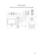
WIRING DIAGRAM  


ONE-FAMILY SYSTEM WITH ONE MONITOR AND ONE CAMERA 


Summary of Contents for OR-VID-CK-1039

Page 1: ...Video Door Entry System Kits 4 Wires Installation Safety Operating Instructions OR VID CK 1039 ...

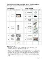
Page 2: ...isitor who calls at the door and controlling the opening of the door and or gate You can develop your installation by adding an optional additional monitor and or a second roadside panel For a safe installation and use please read carefully these instructions and keep them safe Parts Supplied Fittings Supplied Ref Description Illustration Qty Ref Description Illustration Qty A Indoor Monitor 1 F P...

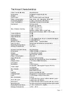
Page 3: ...Operating Temperature 0 40 Storage Temperature 20 60 Outdoor Unit NVC 6104 Specifications Dimensions 39 W x129 H x 23 D mm Weight 0 3Kg W rain shield Input Power DC12V from monitor Power Consumption Max 3W Aspect Material Zinc Alloy Die Casting Wiring Monitor to Camera 4wires Door lock 2Wires Image sensor 1 4 Colour CMOS Camera TV system PAL Resolution 700 TV Lines Video output Composite video sig...

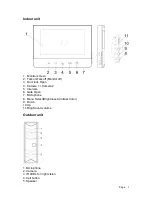
Page 4: ...k off Monitor off 3 Door lock Open 4 Camera 1 Camera 2 5 Intercom 6 Gate Open 7 Microphone 8 Menu Select Brightness Contrast Color 9 Down 10 Up 11 Ring Sound volume Outdoor unit 1 Microphone 2 Camera 3 IR LEDs for night vision 4 Call button 5 Speaker ...

Page 5: ...designed for moderate climates Do not use in high humidity dusty or dirty areas 11 To disconnect or isolate the unit switch off at the socket or remove plug from wall socket Please ensure the plug and socket is easily accessible Warnings 1 Do not install the outdoor unit where it will be exposed to direct sunlight or any strong reflected light Avoid extremely bright locations for the indoor unit a...

Page 6: ...Page 5 WIRING DIAGRAM ONE FAMILY SYSTEM WITH ONE MONITOR AND ONE CAMERA ...

Page 7: ...Page 6 WIRING DIAGRAM ONE FAMILY SYSTEM WITH TWO MONITORS AND TWO CAMERAS ...

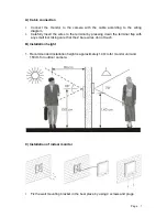
Page 8: ...terminal by pressing down the terminal flap with any small tool taking care that the 2 bare wires do not touch B Installation height 1 Recommended installation height is approximately 140cm for monitor unit and 150cm for outdoor camera C Installation of indoor monitor 1 Fix the wall mounting bracket in the best place by using 4 screws and plugs ...

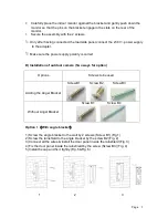
Page 9: ...ty is correct D Installation of outdoor camera Two ways for option Options Screws to be used Adding the Angel Bracket Screw B1 Screw B2 Screw B3 Without Angel Bracket Screw B1 Screw B4 Option 1 With angle bracket 1 Screw the angle bracket to the wall by 2 screws Screw B1 Fig 1 2 Screw the rainshield to the angle bracket by the screw B2 Fig 2 3 Connect all the wires install the door panel inside th...

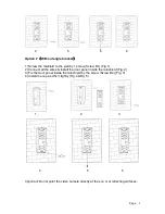
Page 10: ...1 Fig 1 2 Connect all the wires install the door panel inside the rainshield Fig 2 3 Fix the door panel inside the rainshield by the screw Screw B4 Fig 3 4 Install the cap and fix it tightly Fig 4 Fig 5 1 2 3 4 5 5 Important Do not point the video camera directly at the sun or at reflecting surfaces ...

Page 11: ...tor After the visitor is visually identified and if you wish to talk with the visitor touch the button The unit will remain activated for approximately 60 seconds before it automatically shuts off To re activate for continued conversation touch the button and then touch the button 2 Activation of outside unit from monitor unit a Touch the button of the indoor unit at any time and the outdoor camer...

Page 12: ...llation connect it to the terminals at the back of the roadside panel If you want to open the door to let the caller in just touch the button on the indoor monitor This function can only be used when the screen is switched on Important It is essential that the electric latch or lock installed has a mechanical memory 6 Activation of button Connect the automatic gate opener directly to the terminals...

Page 13: ...etergents To clean wipe with a damp cloth from time to time Troubleshooting No Problem Check point 1 No power no picture on monitor Is the AC plug firmly inserted into the AC outlet 2 Power is on but no picture on the monitor Is the cable firmly connected between the monitor and the camera Is the polarity of wires correct between the outdoor camera unit and indoor monitor unit 3 The picture is too...

Reviews: