background image


2

3

/3

4


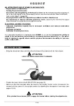
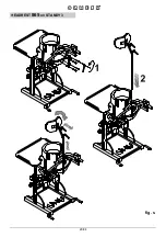
Opening the BACK SUPPORT on STANDY 3


CORRECT  

POSITIONING OF  

TRAVEL STOP 

fig. o 

FIRST MOVE THE TRAY FORWARD AND AWAY (see fig. N on page 2

2

CORRECT  

POSITIONING OF  

TRAVEL STOP 

fig. O 


Opening the BACK SUPPORT on STANDY 4


Summary of Contents for STANDY 3

Page 1: ...INGLESE Cod 22135 12 09 2011 STANDY 4 STANDY 3 STANDY 4 STANDY 3 USE AND MAINTENANCE HANDBOOK STANDING FRAME FOR THE UPRIGHT POSITION STANDING FRAME FOR THE UPRIGHT POSITION ...

Page 2: ......

Page 3: ... STANDY quickly it also con tains practical tips for making the best use of it safely and keeping it in good working order Following the recommendations of this manual will help you achieve the rehabilitative goal for which this aid was developed If after reading it you still have questions contact your retailer who will be happy to help you or call ORMESA directly at 39 0742 22927 send a fax to 3...

Page 4: ......

Page 5: ...epth of the BACK SUPPORT on STANDY 3 18 Adjusting the depth of the BACK SUPPORT on STANDY 4 18 Adjusting the width height and depth of the KNEEPADS on STANDY 3 and STANDY 4 19 Adjusting the HEEL STOPS on STANDY 3 and STANDY 4 20 Adjusting the height of the WORK TABLE on STANDY 3 21 Adjusting the height of the WORK TRAY on STANDY 4 21 Adjusting the depth of the WORK TABLE on STANDY 3 22 Adjusting t...

Page 6: ...asurements and weight conform to the specificati ons in the paragraph T ECHNICAL C HARACTERISTICS on pages 8 and 9 STANDY must be used with the assistance and constant presence of qualified per sonnel or a family member ATTENTION Make sure that all adjustable parts have been locked before each use T o make adjustments while the product is in use follow the instructions in section HOW TO ADJUST STA...

Page 7: ...eels HOW TO STORE AND TRANSPORT THE MEDICAL DEVICE TO AND TRANSPORT THE MEDICAL DEVICE THE DEVICE MUST BE STORED AND PACKED using the Ormesa original pack aging materials unless the guarantee will be voided Once unpacked THE TRANSPORT OF THE DEVICE must be done by ANCHORING ADEQUATELY it to the vehicle When travelling by plane or in the car DO NOT SUBJECT THE FOLDED FRAME TO LOADS THAT especially ...

Page 8: ...Y SURFACE BECAUSE THEY COULD TIP OVER and because the wood or covering could be seriously damaged DO NOT ALLOW OTHER PEOPLE TO USE THE PRODUCT NOT EVEN FOR PLAYING NEVER LEAVE THE USER UNATTENDED OR NEAR OPEN FLAME OR STAIRS NEVER LEAVE STANDY PARKED FOR A LONG TIME IN DIRECT SUNLIGHT OR NEAR SOURCES OF HEAT THIS WILL AVOID OVERHEATING THE DEVICE AND DISCOLOURING THE UPHOLSTERY DO NOT USE THE PROD...

Page 9: ...6 34 HOW TO MOVE STANDY ATTENTION IT CAN TIP OVER IF TILTED MORE THAN 20 STANDY 3 STANDY 4 fig A fig A ...

Page 10: ...nder A cm B cm C cm VOLUME m WEIGHT kg STANDY 3 80 80 84 0 537 33 STANDY 4 85 80 93 0 632 42 ATTENTION CUT WITHOUT PRESSING TOO HARD SO AS NOT TO DAMAGE THE CONTENTS OF THE BOX REMOVE STANDY FROM THE BOX WITHOUT DRAGGING REMOVING STANDY FROM THE BOX ...

Page 11: ...adjustable painted with non toxic polyester and epoxy polyester powder paints Ergonomic work table in plastic laminated wood height adjustable removable Semi rigid side protections Kneepads width depth and height adjustable Padded depth adjustable back support Padded height adjustable chest support Heel stops width and depth adjustable Footrest in aluminium with diamond pattern non skid surface Wh...

Page 12: ... with non toxic polyester and epoxy polyester powder paints Work tray in plastic laminated wood height adjustable removable Kneepads width depth and height adjustable covered with fireproof material Arm support adjustable chromed Padded depth adjustable back support Padded height adjustable chest support Heel stops width and depth adjustable Footrest in aluminium with diamond pattern non skid surf...

Page 13: ...le of using the aid THE DEVICE IS INTENDED FOR USE at home in specialized rehabilitation centres in hospital gymnasiums in nursing homes DO NOT LEAVE THE USER UNATTENDED OR NEAR OPEN FLAME OR STAIRS THE AID MAY BE USED OUTDOORS ONLY IF THE SURFACE IS FLAT AND WELL PAVED AND PROTECTED FROM BAD WEATHER WHAT DOES STANDY DO STANDY HAS BEEN DESIGNED to provide training in achieving an erect position fo...

Page 14: ...e phenomena facilitates peristalsis facilitates circulatory functions It is especially important to emphasize that STANDY is an aid that increases the ability to adapt to the surrounding environment by increasing personal autonomy i e the possi bility of relating to oneself others and the physical environment the ability to put one self in contact with HOW STANDY WORKS Bring the wheelchair close u...

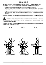
Page 15: ...n the feet should be equidistant from the centre of the sup port platform the pelvis symmetrical and aligned with the trunk and the trunk and legs extended If there is sufficient trunk control the chest support may be lowered or removed see p 16 ATTENTION THE STANDER MUST ALLOW THE USER TO PERFORM ACTIVITIES IN A CORRECT AND FACILITATING POSITION AND MUST NOT SERVE TO KEEP THE PERSON STILL OR IMMO...

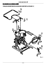
Page 16: ...13 34 HOW TO ASSEMBLE STANDY fig e Fitting the WORK TABLE and the BACK SUPPORT on STANDY 3 ...

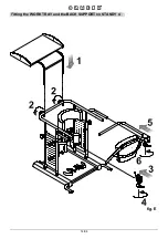
Page 17: ...14 34 fig E Fitting the WORK TRAY and the BACK SUPPORT on STANDY 4 ...

Page 18: ...th and depth 4 the position of the thoracic support 5 the position of the tray which must be set by checking the user s height from under the elbow to the ground minimum height In those cases where it is not possible to take this measurement with the person standing measure the dis tance from bent elbow to feet with the user lying down To operate the handle STANDY 4 only the tray must be moved awa...

Page 19: ...justing the height of the CHEST SUPPORT on STANDY 4 It can be removed for users with sufficient trunk control Adjusting the height of the CHEST SUPPORT on STANDY 3 It can be removed for users with sufficient trunk control ...

Page 20: ...t adjustment indicator fig g height adjustment indicator fig G Adjusting the height of the HAND SUPPORT RING and BACK SUPPORT on STANDY 3 Adjusting the height of the HAND SUPPORT RING and BACK SUPPORT on STANDY 4 ...

Page 21: ...18 34 fig h fig H Adjusting the depth of the BACK SUPPORT on STANDY 3 Adjusting the depth of the BACK SUPPORT on STANDY 4 ...

Page 22: ...19 34 REAR VIEW REAR VIEW SIDE VIEW fig I Adjusting the width height and depth of the KNEEPADS on STANDY 3 and STANDY 4 ...

Page 23: ...20 34 fig L Adjusting the HEEL STOPS on STANDY 3 and STANDY 4 ...

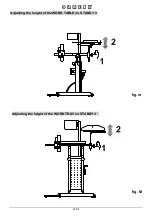
Page 24: ...WORK TABLE on STANDY 3 21 34 Adjusting the height of the fig m fig M WORK TRAY on STANDY 4 Adjusting the height of the ...

Page 25: ...WORK TRAY on STANDY 4 during use 22 34 Adjusting the depth of the WORK TABLE on STANDY 3 fig n Adjusting the depth of the fig N ...

Page 26: ...ning the BACK SUPPORT on STANDY 3 CORRECT POSITIONING OF TRAVEL STOP fig o FIRST MOVE THE TRAY FORWARD AND AWAY see fig N on page 22 CORRECT POSITIONING OF TRAVEL STOP fig O Opening the BACK SUPPORT on STANDY 4 ...

Page 27: ...HANDLE on STANDY 4 fig P The handle that moves the back support must be removed using the wrench provided in the following cases 1 If it is not used autonomously by the user 2 When accessory 865 must be added see page 30 fig S ...

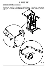
Page 28: ...ACCESSORIES SIDE SUPPORT 857 on STANDY 3 Accessory 857 consists of a side support for the pelvis when it is deviated with respect to the vertical axis due to a user position determined by for example scoliosis shortening of a lower limb etc ...

Page 29: ...PPORT 857 on STANDY 4 Accessory 857 consists of a side support for the pelvis when it is deviated with respect to the vertical axis due to a user position determined by for example scoliosis shortening of a lower limb etc ...

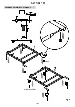
Page 30: ...27 34 4 WHEEL SET 861 on STANDY 3 M12X30 SCREW PLUG fig r ...

Page 31: ...28 34 4 WHEEL SET 861 on STANDY 4 M12X30 SCREW PLUG fig R ...

Page 32: ...29 34 HEADREST 865 on STANDY 3 fig s ...

Page 33: ...30 34 HEADREST 865 on STANDY 4 fig S ATTENTION Remove the handle before mounting the headrest page 24 fig P ...

Page 34: ...31 34 FRONT FOOT RESTRAINTS with BELTS 902 on STANDY 3 BLACK Ø8 WASHER Ø8 WASHER M8x35 SCREW fig t ...

Page 35: ...32 34 FRONT FOOT RESTRAINTS with BELTS 902 on STANDY 4 BLACK Ø8 WASHER Ø8 WASHER M8x35 SCREW fig T ...

Page 36: ......

Page 37: ...from purchase Clean and disinfect the device and its accessories regularly following the instruc tions provided below Cleaning the painted and chrome plated frame Clean painted a nd chromed parts with a soft cloth dipped in alco hol diluted with water Do not grease the adjustable parts Cleaning the upholstery Clean the upholstery with a soft cloth dipped in water and a neutral detergent Cleaning t...

Page 38: ... OR OTHER FACTORY AUTHORIZED SERVICE CENTRE ANY OTHER SOLUTION WILL RESULT IN THE USER AND THE THIRD PARTY MAINTAINER FULLY RESPONSIBLE FOR THE RESULTS OF THEIR WORK AND THE MANUFACTURER WILL ONLY BE LIABLE FOR ORIGINAL DEFECTS OF MATERIALS OR WORKMANSHIP If the product is to be disposed of it must be done according to the law in the country of destination CUSTOMER SERVICE AND SPARE PARTS REUSE On...

Page 39: ......
Page 40: ...Dealer The technical Data and information given in this handbook are not binding ORMESA reserves the right to carry out any necessary change without prior notice or replacements PRODUCT TESTED BY TÜV BERLIN FDAREGISTERED USA ...

Reviews: