background image


9 / 41 


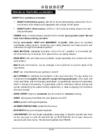
TECHNICAL FEATURES and MODELS 


GIUDITTA is available in 2 models: 

  GIUDITTA B30 (tilt-in-space): with 20 cm front solid swivelling wheels and 30 cm 

rear wheels; drum brakes are engageable with a single control pedal.  

  GIUDITTA  B12  (tilt-in-space):  with  four  12cm  solid  swivelling  wheels,  the  rear 

ones with brakes 

-  FRAME made of chromed steel, painted with non-toxic epoxy powder paint. Narrow 

base to facilitate entering elevators 

-  Strong  semi-elastic  SEAT  and  BACKREST  in  plastic  cord  gives  an  excellent 

comfortable  sitting  position,  avoids  the  user  sliding  forwards  and  helps  prevent  skin 
brakedown through its breathable qualities 

-  SEAT  BOTTOM:  adjustable inclination  from 10° to 27°; available  in four widths (36, 

40, 45 and 50 cm); inclined by 10° to prevent the u ser sliding forward.  

-  HEADREST wide and wrap-around, padded, height-adjustable, with vertical and front-

back rotation 

-  BACK  wide  and  retentive,  can  be  arranged  in  four  positions  to  vary  the  depth  of  the 

seat bottom 

-  SEAT low, to facilitate the user getting on and off 

-  GAS  SPRING  for  adjusting  the  inclination  of  the  seat  and  back.  The  gas  spring  is  a 

mechanism that supports the patient's weight during adjustments of the back and 
of the seat tilting, with the following advantages: a) significantly reduces the assistant's 
effort  in  raising  and  lowering;  b)  guarantees  uniform  movement  without  jerking  and 
avoids  unbalancing  the  patient  during  adjustment;  c)  allows  stopping  the  inclination 
wherever desired 

-  UPHOLSTERY fireproof, breathable and removable for machine washing 

-  SIDES, swing away to facilitate the user getting on and off 

-  ARMS padded and height-adjustable 

-  CORNER PROTECTORS padded for the knees 

- FOOTRESTS flip up and height-adjustable  

-  LEG  SUPPORT  tilt- and  height  adjustable, swing-away  to  help  the  operator  get  close 

as  the  user  gets  on  and  off,  and  with  flip  up  FOOTPLATES  for  an  easy  access  to 
elevators and small rooms. Provided with padded CALFRESTS.  


Summary of Contents for Giuditta B12

Page 1: ...USA cod 22837 27 09 12 USE AND MAINTENANCE HANDBOOK tilt in space wheelchair model B30 tilt in space wheelchair model B12 ...

Page 2: ......

Page 3: ...ul to fully understand its contents In addition to helping you become familiar with the device quickly it also contains practical tips for making the best use of it safely and keeping it in good working order If after reading it you still have questions contact your retailer who will be happy to help you or call INNOVATION IN MOTION directly at 1 260 665 2769 send a fax to 1 260 665 3047 or send a...

Page 4: ...HE INCLINATION OF THE SEAT BOTTOM TILT IN SPACE 18 CLOSING THE FOOTRESTS 19 ADJUSTING THE FOOTRESTS IN HEIGHT 19 TURNING THE LEGRESTS 20 REMOVING THE LEGRESTS 21 ADJUSTING THE LEGREST INCLINATION 22 TURNING THE CALFRESTS 23 ADJUSTING THE HEIGHT OF THE ARMRESTS 23 OPENING THE SIDE SUPPORTS 24 ADJUSTING THE HEADREST 25 ADJUSTING THE DEPTH OF THE SEAT 26 REMOVING THE UPHOLSTERY FOR THE WASHING 27 ASS...

Page 5: ...sons who have read the rules and instructions in this manual The doctor must check that the use of the GIUDITTA wheelchair and its accessories conforms to current laws regulations and standards The wheelchair must be used by persons of the BODY SIZE AND WEIGHT specified in the paragraph TECHNICAL FEATURES on pages 10 and 11 The wheelchair must be guided by persons of suitable height and weight to ...

Page 6: ...wn on page 39 40 of the manual must be ONLY MADE by a SPECIALIZED SERVICE CENTER in the maintenance of mechanical aids for disables otherwise warranty and marking will be voided Any CHANGES in the product and the REPLACEMENT WITHOUT ORIGINAL PARTS OR COMPONENTS ARE NOT AUTHORIZED REFER ONLY TO ORMESA otherwise warranty and marking will be voided In case of DOUBT about the SAFETY of the product or ...

Page 7: ...e subject to wear and tear such as the upholsteries and the wheels HOW TO STORE AND TRANSPORT THE MEDICAL DEVICE THE DEVICE MUST BE STORED AND PACKED using the Ormesa original packaging materials unless the guarantee will be voided Once unpacked THE TRANSPORT OF THE DEVICE must be done by ANCHORING ADEQUATELY it to the vehicle When travelling by plane or in the car DO NOT SUBJECT THE FOLDED FRAME ...

Page 8: ...R UNATTENDED ESPECIALLY ON THE BEACH OR NEAR A RAVINE SWIMMING POOL SLOPE OPEN FLAME OR STAIRS DO NOT CARRY THE USER OVER ROUGH OR STEEP SURFACES OR STAIRS NEVER LEAVE THE AID PARKED ON SLOPING GROUND DO NOT CLIMB CURBS OR STEPS WITH JUST THE SIDE WHEELS front or back because it could tip over see fig on page 7 When the SEAT is COMPLETELY TILTED BACKWARDS and the BACK is COMPLETELY RECLINED DO NOT...

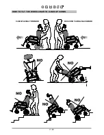
Page 9: ...7 41 HOW TO TILT THE WHEELCHAIR TO CLIMB UP CURBS CLIMB FACING FORWARD DESCEND FACING BACKWARD ...

Page 10: ...on on pages 39 and 40 The aid is intended for those adults who do not have control of their trunk and or that tend to slide on one side or to sit on their coccyx rather than on their gluteus and allows convalescents disabled elderly etc TO REMAIN IN IT FOR EXTENDED PERIODS LYING DOWN AS AN ALTERNATIVE TO STAYING IN BED The conformation and reclining of the backrest the seat tilting and the reclini...

Page 11: ... back rotation BACK wide and retentive can be arranged in four positions to vary the depth of the seat bottom SEAT low to facilitate the user getting on and off GAS SPRING for adjusting the inclination of the seat and back The gas spring is a mechanism that supports the patient s weight during adjustments of the back and of the seat tilting with the following advantages a significantly reduces the...

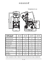
Page 12: ...t 40 cm 35 with B at 43 cm 25 with B at 36 cm 27 with B at 40 cm 30 with B at 43 cm 28 with B at 42 cm 30 with B at 45 cm 35 with B at 47 cm 26 with B at 42 cm 28 with B at 45 cm 32 with B at 47 cm kg 32 kg 140 size 36 size 40 size 45 size 50 cm 40 cm 36 40 43 cm 70 75 cm 56 cm 59 10 27 kg 33 kg 140 cm 45 cm 42 45 47 cm 70 75 cm 61 cm 64 10 27 kg 34 kg 140 cm 50 cm 42 45 47 cm 70 75 cm 66 cm 69 10...

Page 13: ...e 45 size 50 cm 40 cm 36 40 43 cm 70 75 cm 56 cm 59 10 27 kg 30 5 kg 140 cm 45 cm 42 45 47 cm 70 75 cm 61 cm 64 10 27 kg 31 5 kg 140 cm 50 cm 42 45 47 cm 70 75 cm 66 cm 69 10 27 kg 32 5 kg 140 Hypen separated numbers indicate the minimum and maximum range of adjustment 26 with B at 36 cm 28 with B at 40 cm 35 with B at 43 cm 25 with B at 36 cm 27 with B at 40 cm 30 with B at 43 cm 28 with B at 42 ...

Page 14: ...TTENTION CUT WITHOUT PRESSING TOO HARD PRESS GENTLY WITH THE KNIFE SO AS NOT TO DAMAGE THE CONTENTS OF THE BOX REMOVE THE ACCESSORIES TILT THE BOX AND TAKE CARE NOT TO SCRAPE THE CONTENTS DURING REMOVAL Size 40 Size 36 Size 45 Size 50 40 41 42 43 65 84 0 410 0 410 0 410 0 454 75 65 84 75 65 84 75 71 81 79 ...

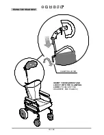
Page 15: ...13 41 FIXING THE HEADREST CLAMPING LEVER INSERT THE HEADREST AND LOCK IT WITH THE CLAMPING LEVER TO ADJUST THE HEADREST SEE PAGE 24 ...

Page 16: ...14 41 FIXING AND POSITIONING THE LEGREST SIDE VIEW ...

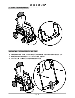
Page 17: ...T THE LEGRESTS ON THE TWO PINS AS SHOWN IN THE FIGURE 2 ROTATE THE LEGRESTS TILL THEY ARE CLOSED 3 A CLICK MEANS THEY ARE NOW LOCKED MAKE SURE THAT THE LEGRESTS ARE INSERTED AND DO NOT TURN 4 PUSH DOWN THE LEGRESTS ...

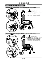
Page 18: ...TTENTION BEFORE THE USER GETS IN OR OUT OF THE WHEELCHAIR AND BEFORE ADJUSTING ANY OF ITS PARTS YOU MUST BRAKE THE AID BRAKING THE WHEELCHAIR B12 MODELS with four 12cm wheels LOCKS UNLOCKS ATTENTION BEFORE THE USER GETS IN OR OUT OF THE WHEELCHAIR AND BEFORE ADJUSTING ANY OF ITS PARTS YOU MUST BRAKE THE AID ...

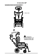
Page 19: ...17 41 ADJUSTING THE TILT OF THE BACKREST REAR VIEW ATTENTION THIS ADJUSTMENT CAN BE DIFFICULT WITHOUT THE PRESENCE OF THE USER ...

Page 20: ...18 41 ADJUSTING THE INCLINATION OF THE SEAT BOTTOM TILT IN SPACE REAR VIEW ...

Page 21: ...CLOSING THE FOOTRESTS ADJUSTING THE FOOTRESTS IN HEIGHT 1 UNSCREW THE NUTS AND REMOVE THE SCREWS USING THE KEYS SUPPLIED 2 POSITION THE FOOTREST AT THE DESIRED HEIGHT 3 INSERT THE SCREWS AND TIGHTEN THE NUTS ...

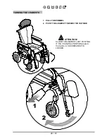
Page 22: ...20 41 TURNING THE LEGRESTS 1 PULL THE POMMEL 2 PIVOT THE LEGREST TOWARD THE OUTSIDE ATTENTION CLOSE THE LEGREST JUST PIVOTING IT TILL ITS INITIAL POSITION toward the inside A CLICK MEANS IT IS LOCKED ...

Page 23: ...21 41 REMOVING THE LEGRESTS 1 PULL THE POMMEL 2 TAKE THE LEGREST OUT ...

Page 24: ...22 41 ADJUSTING THE LEGREST INCLINATION 1 PULL THE LOCKING LEVER 2 AT THE SAME TIME ADJUST THE INCLINATION OF THE LEGREST LOCKING LEVER ...

Page 25: ...23 41 TURNING THE CALFRESTS ADJUSTING THE HEIGHT OF THE ARMRESTS ...

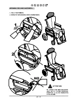
Page 26: ...24 41 OPENING THE SIDE SUPPORTS 1 PULL THE POMMEL 2 ROTATE THE SIDE BOLSTER DOWNWARDS ATTENTION TO CLOSE THE SIDE BOLSTER JUST LIFT IT TO THE VERTICAL POSITION A CLICK INDICATES IT IS LOCKED ...

Page 27: ... LOOSEN THE CLAMPING LEVER 2 ADJUST THE HEIGHT OF THE HEADRES TIGHTEN THE CLAMPING LEVER CLAMPING LEVER CLAMPING LEVER 1 LOOSEN THE THREE CLAMPING LEVERS 2 ADJUST THE INCLINATION AND DEPTH OF THE HEADRESTTIGHTEN THE CLAMPING LEVERS ...

Page 28: ...CREWS 2 MOVE THE BACK TO THE DESIRED POSITION 3 INSERT THE SCREWS AND TIGHTEN THE NUTS SEAT WIDTH CM 36 SEAT WIDTH CM 40 SEAT WIDTH CM 45 SEAT WIDTH CM 50 HOLES TO ADJUST SEAT IN DEPTH HOLES TO ADJUST SEAT IN DEPTH HOLES TO ADJUST SEAT IN DEPTH HOLES TO ADJUST SEAT IN DEPTH ...

Page 29: ...27 41 REMOVING THE UPHOLSTERY FOR THE WASHING STUDS FOR THE WASHING FOLLOW THE INSTRUCTIONS GIVEN ON PAGE 39 CLEAN THE PADS OF THE LEGRESTS WITH A SPONGE DO NOT MACHINE WASH ...

Page 30: ...28 41 REAR VIEW OF THE BACK BELTS WITH STUDS ALWAYS ATTACH THE BELTS ON THE FIRST TWO CORDS AS IN THE FIGURE ABOVE WE RECOMMEND TO FIX THE PADS WITH THE ARMRESTS LOWERED ...

Page 31: ... fig 2 b Tighten well the clamping lever and the handwheels of the table fig 1 and 2 c Before changing the inclination of the seat bottom tilt in space MAKE SURE THAT THERE ARE NO HOT OBJECTS or LIQUID CONTAINERS on the table that could cause DAMAGE or BURNS when they tip over CLAMPING LEVER HANDWHEEL HANDWHEEL FIRST INSERT THE LEFT TABLE ROD LONGER TO FACILITATE INSERTION ...

Page 32: ...30 41 ADJUSTING THE DEPTH OF THE TABLE ADJUSTING THE TILT OF THE TABLE CLAMPING LEVER HANDWHEEL ...

Page 33: ...31 41 FIXED TABLE 824 F ATTENTION TIGHTEN WELL THE HANDWHEELS OF THE TABLE HANDWHEEL FIRST INSERT THE LEFT TABLE ROD LONGER TO FACILITATE INSERTION CHEST STRAP 828 REAR VIEW ...

Page 34: ...32 41 ABDUCTION BLOCK 834 ATTENTION TIGHTEN WELL THE HANDWHEEL ...

Page 35: ...33 41 FOOTREST LOCK 914 It locks the two footrests together to form one unit A ASSEMBLING the footrest lock WRENCH M5x30 SCREWS BUSHINGS LOCKING MECHANISM FOR SINGLE FOOTREST NUTS WRENCH ...

Page 36: ...34 41 B UNLOCKING the footrest lock LOCKING LEVER C OPERATING the footrest lock LOCKING LEVER ...

Page 37: ...35 41 REMOVABLE FOOTPLATE COVERING 892 ATTENTION IN ORDER TO FIX THE PADDED COVER OF THE FOOTREST IT IS NECESSARY TO FIX THE 914 FOOTREST LOCK FOOTREST LOCK 914 VIEW FROM BELOW OF THE FOOTREST ...

Page 38: ...36 41 PADDED LEG PANEL 916 in alternative to the calf rests 1 REMOVE THE CALF RESTS ...

Page 39: ...37 41 2 FIX THE LEG PANEL ...

Page 40: ...38 41 REMOVABLE TABLE COVERING 896 VIEW FROM BELOW OF THE TABLE ...

Page 41: ...E Clean and disinfect the painted and chromed parts of the seat and base with a soft cloth dipped in a household detergent and disinfectant such as alcohol diluted in water WASHING AND DISINFECTING THE UPHOLSTERY Wash the upholsteries of the accessories 834 ABDUCTION BLOCK 892 REMOVABLE FOOTPLATE COVERING 896 REMOVABLE TRAY COVERING 916 PADDED LEG PANEL with neutral household soap After rinsing dr...

Page 42: ... anoint the parts exposed to salt corrosion such as chrome bolts and screws EXTRAORDINARY OR CORRECTIVE MAINTENANCE EXTRAORDINARY MAINTENANCE MEANS ANYTHING DONE TO THE PRODUCT THAT IS NOT MENTIONED ABOVE IN THE PARAGRAPH ORDINARY MAINTENANCE WE RECOMMEND THAT THE USER RETAILER AND HEALTH FACILITIES ENTRUST ALL EXTRAORDINARY OR CORRECTIVE MAINTENANCE TO THE MANUFACTURER OR OTHER FACTORY AUTHORIZED...

Page 43: ...ct it is required that 1 a doctor or therapist verifies that the aid is appropriate and adequate to meet the dimensional functional and postural needs of the new user and if all its components are suitable appropriate for him You should also consider that the marking and the manufacturer s responsibility for safety requirements for the product remain only if the original product still has not chan...

Page 44: ...ook are not binding ORMESA reserves the right to carry out any necessary change without prior notice or replacements DISTRIBUTOR FOR USA INNOVATION IN MOTION 201 Growth Parkway ANGOLA IN 46703 P 1 260 665 2769 F 1 260 665 3047 Toll free number 800 327 0681 E mail iim mobility usa com ...

Reviews: