System manual
SM0974080 A 02
7
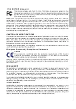
Figure 1
1
13
14
2
Crimp side
Female connector
4
1
2
3
Monitor side 16p
Connector housing
4p Moulded female connector
camera side
Power
14p female connector
display side
Lenght 500mm
Units in mm
1
2
3
4
5
6 7
Camera side
Front side
4p Female connector
5. Electrical connections Sets
Art no. 0303070
Cable 0,5m Economy Line Display, see figure 1.
Connections to the Monitor.
1 = Red
= Power
2 = White
= 0V
3 = Blue
= Camera 1
4 = Brown
= Camera 2
5 = White/Yellow
= Camera 3
6 = Grey
= Aux 1
7 = Yellow
= Aux 2
8 = Coax core
= Video
9 = Coax shielding = Video GND
10 = Red
= Power
11 = Black
= 0V
12 = N.C.
13 = N.C.
14 = N.C.
Connections to the camera.
1 = Coax core
= Video
2 = Coax shielding
= Video GND
3 = Red
= Power
4 = Black
= 0V