11
make contact with the surface; only the mirror retaining
clips will. Place the three springs onto the three exposed
threaded shafts
(Figure 16a). (The XX12g mirror is
shown, but the procedure is similar for the XX14g and
XX16g.) Lower the end ring onto the mirror cell so the
threaded shafts pass through it, and the end ring rests on
the springs
(16b). Add a nylon washer to each collima-
tion knob and thread the collimation knobs through the
end ring and onto the threaded shafts (
16c). Make sure
the knobs have at least three full turns of engagement
on the shafts. The mirror cell is now almost ready to be
installed onto the lower tube section.
4. Check to make sure that the three mirror retaining clips
are properly tensioned (XX12g only,
Figure 3a). If they
are too tight, the pinching of the mirror’s edge will dis-
tort the images you see through the telescope. But if they
are too loose, the mirror could shift or even fall out if it is
tilted severely. With the mirror in its cell facing up, use a
Phillips screwdriver to loosen the two screws on one of
the clips until you can easily move the small metal plate
underneath the screw heads. Then gradually tighten both
screws just until the metal plate is no longer loose – no
tighter! Repeat this with the other two retaining clips. Now
the clips are properly tensioned.
5. Assembling the end ring (and mirror assembly) back onto
the tube can be a bit tricky. This is because the large
diameter and thin metal of the tube will cause the tube
to become somewhat out of round once the end ring is
removed. To assemble the rear end ring (with mirror and
mirror cell now connected) to the tube, stand the lower
section of the tube up vertically so the raw edge of the
tube is up. Line up the threaded holes in the edge of the
end ring with the holes in the end of the tube. Then, lower
the entire assembly onto the tube. (Be careful to avoid
finger pinching during this step!) There may be a bulge in
the perimeter of the tube that prevents the end ring from
fully seating onto the tube
(Figure 17). Press against this
bulge, and the entire mirror cell assembly should seat
onto the tube. Now, replace the Phillips screws that fas-
ten the rear end ring to the tube.
Before assembling the rest of the optical tube, you should con-
sider how you want to mount the optical tube on the base. We
recommend mounting the lower tube section onto the base
first, THEN adding the counterweights, then the truss poles
and upper tube section. Alternatively, you could complete the
assembly of the entire optical tube first, then hoist the whole
thing onto the base. But for that we strongly recommend get-
ting a second person to help with the lifting – at least for the
XX14g and XX16g. For these instructions, we will outline the
procedure for installing the lower tube section on the mount
first, then building the rest of the OTA from there.
Mounting the lower tube section (only) on
the Base
1. Loosen the altitude clutch knob slightly so the altitude
trunnion can rotate with relatively little resistance.
Note: To keep the bottom tube section as light as
possible for lifting during installation, do not install
the counterweights until after the tube is installed
on the base (see step 4 below).
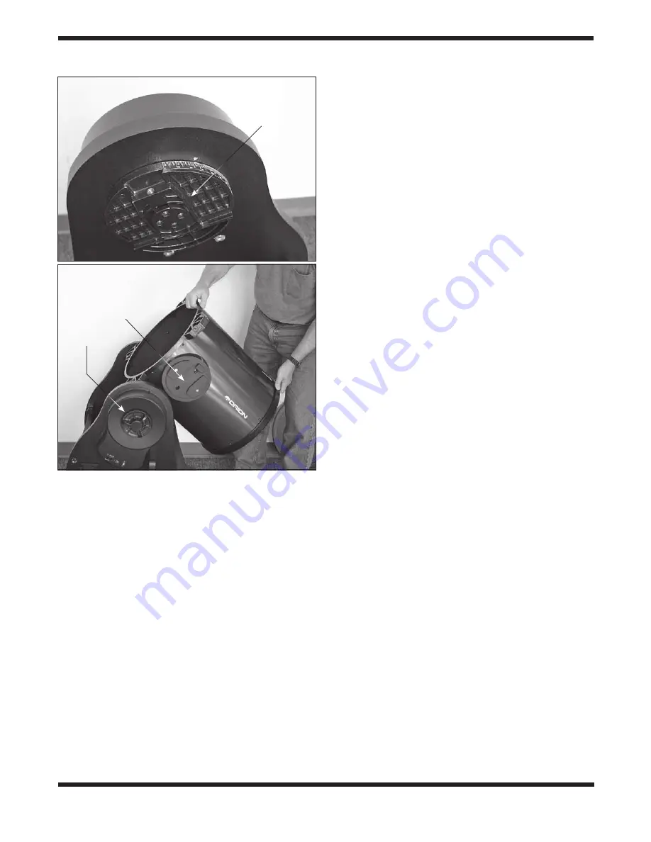
2. The left altitude side bearing on the optical tube has a
dovetail slot that slides onto the altitude axis trunnion on
the inside of the left side panel (
Figure 18a). We rec-
ommend orienting the trunnion such that the threaded
hole for the tube connecting knob is at about a 45-degree
angle from horizontal. If the altitude trunnion is oriented
differently, you’ll have to adjust the angle of the telescope
tube accordingly to mount it. Grasp the tube section as
shown in
Figure 18b and lift it. Slide the tube’s dovetail
altitude bearing into the mating receptacle of the altitude
trunnion on the base. Once seated in the base, the tube
will freely rotate to a vertical position due to its bottom-
heavy imbalance. Maintain your grip on the tube and
gently guide it to the resting, vertical position.
Figure 18. a)
Altitude axis trunnion on left side panel.
b)
Grasp
both ends of the lower tube section to lift it, then lower it into the
base, sliding the dovetail slot in the tube’s left altitude bearing into
the mating part of the trunnion.
Altitude axis
trunnion
Altitude side
bearing (dovetail)
Altitude
clutch knob
a.
b.
a.


