9
either side of 0 – there are no (+) or (-) signs. When the telescope
is pointed north of the equator, actual values of Dec. are negative.
For example, the coordinates for the Orion Nebula (M42) are:
R.A. 5 hr 35.4 min, Dec. -5° 27'
That’s 5 hours and 35.4 minutes in right ascension, and -5
degrees and 27 arc-minutes in declination (there are 60 arc-
minutes in 1 degree of declination).
Before you can use the setting circles to locate objects, the
mount must be polar aligned, and the setting circles must be
calibrated. The easiest way to calibrate the setting circles is to
point the telescope at an identifiable bright star, center it in the
eyepiece, then set the setting circles to the star’s published
coordinates, which you can find in a star atlas or astronomical
software program, or perhaps on the internet.
Calibrating the Setting Circles
Using a star atlas or astronomy planetarium program, identify
a bright star visible in your sky. Some smartphone astronomy
apps allow you to hold your phone up to the sky and the app
will identify the stars and constellations visible in the direction
you’re pointing to. Note the right ascension and declination
coordinates of the star.
Let’s take as an example Altair, in the constellation Aquila. Its
coordinates are:
R.A. 19 hr 51 min, Dec 8° 52'
1. Loosen the R.A. and Dec. lock knobs on the equatorial
mount, so the telescope optical tube can move freely.
2. Point the telescope at Altair. Lock the R.A. and Dec. lock
knobs. Center the star in the eyepiece with the slow-motion
control cables.
3. Rotate the R.A. setting circle until the metal arrow indicates
19 hr 51 min.
4. Then rotate the Dec. setting circle until the metal arrow indi-
cates +8° 52'
Note that the setting circles may be a little hard to rotate. But
just grab it firmly around the edge and twist it and it will rotate.
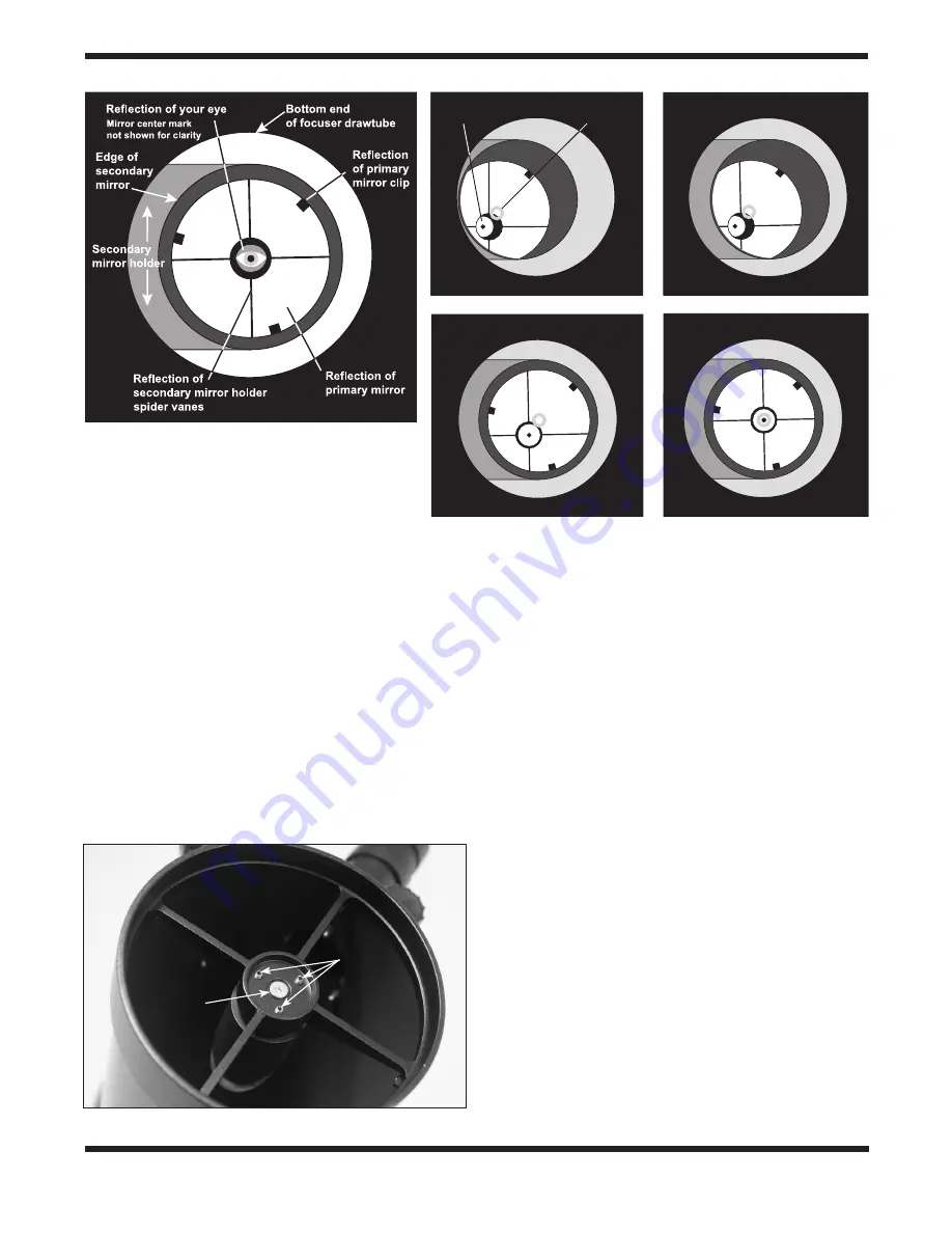
Figure 15.
Collimating the optics.
(
a
)
When the mirrors
are properly aligned, the view down the focuser drawtube
should look like this
(
b
)
With the collimation cap in place,
if the optics are out of alignment, the view might look
something like this.
(
c
)
Here, the secondary mirror is
centered under the focuser, but it needs to be adjusted
(tilted) so that the entire primary mirror is visible.
(
d
)
The
secondary mirror is correctly aligned, but the primary
mirror still needs adjustment. When the primary mirror is correctly aligned, the “dot” will be centered, as in
(
e)
.
a.
Primary mirror
center mark
Reflective surface
of collimation
cap
b.
c.
d.
e.
Figure 16.
Secondary mirror collimation screws.
Central threaded
adjustment screw
(rarely needs
adjustment)
Tip-tilt
adjustment
screws


