5
Preparing the Telescope
for Operation
Aligning and Using the Red Dot Finder Scope
The included red dot finder scope (H) makes pointing your tele-
scope almost as easy as pointing your finger! It’s a non-magni-
fying aiming device that superimposes a tiny LED-illuminated
red dot on the sky, showing exactly where the telescope is
pointed. It permits easy object targeting prior to observation in
the higher-power main telescope.
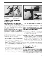
Before you can use the red dot finder scope, you must remove
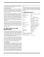
the tab sticking out from the battery compartment (Figure 10).
Doing so will allow the pre-installed 3V CR-2032 button cell bat-
tery to make contact with the finder scope’s electronic circuitry
to power the finder’s red LED illuminator. The tab can then be
discarded.
To use the red dot finder scope properly, it must be aligned with
the main telescope. This is easiest to do during daylight hours,
before observing at night. Follow this procedure:
1. First, remove the dust cap (J) from the front of the telescope.
2. With the star diagonal and 25mm eyepiece already in place,
point the telescope at a well-defined land target (e.g., the
top of a telephone pole) that’s at least a quarter mile away.
Center the target in the eyepiece by moving the optical
tube by hand, with the altitude and azimuth tension knobs
slightly loosened to allow easy movement in both axes),
then by turning the slow-motion cables as needed to center
the target object.
3. Now that a distant target is centered in the main telescope’s
eyepiece, turn on the red dot finder scope by sliding the
power switch to ON (refer to Figure 10). Position your
eye at a comfortable distance from the rear of the unit.
Look through the round window of the finder scope with
both eyes open to see the illuminated red dot. The target
object should appear in the field of view somewhere near
the red dot.
NOTE: This finder has two brightness settings. When the
switch is set all the way over to the ON position, the red dot
is brightest. But in between the OFF and ON positions is a
middle setting in which the red dot is dim. Typically the dim
setting is used under dark skies and the brighter setting is
used under light-polluted skies or in daylight.
4. You’ll want to center the target object on the red dot. To do
so, without moving the telescope, use the finder scope’s
vertical and horizontal adjustment knobs (shown in Figure
10) to position the red dot on the object.
5. When the red dot is centered on the distant object, check
to make sure the object is still centered in the telescope’s
eyepiece. If it isn’t, re-center it then adjust the finder
scope’s alignment again. When the object is centered in
the telescope eyepiece and on the finder scope’s red dot,
the finder scope is properly aligned with the telescope. The
red dot finder scope’s alignment should be checked before
every observing session.
At the end of your observing session, be sure to slide the power
switch on the red dot finder scope to OFF to preserve battery
life.
2. Using the VersaGo
E-Series Mount
The VersaGo E-Series mount allows motion in two axes: altitude
(up and down) and azimuth (left and right). Hence, the VersaGo
E-Series is an “altazimuth” mount. To make coarse movements
of your instrument, loosen the azimuth tension knob and/or the
altitude tension knob (see Figure 5) to slew the instrument to
your target. Then lightly retighten the knob(s). When set to the
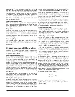
Figure 8. Install the diagonal
and an eyepiece in the
focuser as shown.
Figure 10. The red dot finder scope has vertical and (inset)
horizontal adjustment knobs for aligning it with the telescope.
Battery compartment
Vertical
adjustment
knob
Power switch
Tab
Horizontal
adjustment
knob
Opposite side
8
9
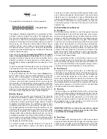
Figure 9. The fully assembled
VersaGo E-Series 90mm
Altazimuth Refractor


