4
2. Assembly
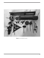
Refer to
Figures 1 and 2 and the parts list at left for identifica-
tion of specific parts during assembly.
1. Stand the tripod (A) upright and spread the legs apart.
Keep the tripod legs at their shortest (fully retracted) length
for now; you can extend them to a more desirable length
later, after the mount is fully assembled.
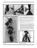
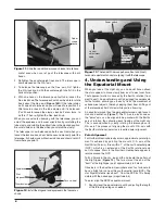
2. To attach the accessory tray (B), place a hooked tab on
one of the three corners of the tray over the screw in the
leg collar, as shown in
Figure 3A. Connect the tray to the
other two legs in the same manner (
3B), then tighten all
three of the tray lock knobs (
3C) to secure the tray in place.
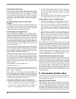
3. Now you’ll install the equatorial mount (C) onto the tripod.
Remove the azimuth tension knob from the bottom of the
mount; the thin plastic gasket should be kept on
(Figure
4). Then place the mount on the tripod’s mounting plat-
form, inserting the base into the hole in the mounting
platform. Then replace the tension knob, turning the knob
clockwise to tighten the mount on the tripod (
Figure 5).
4. Next, thread the counterweight shaft (M) into its receptacle
as shown in
Figure 6A.
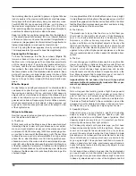
5. To slide the counterweight (E) onto the counterweight
shaft, first remove the Philips screw and washer from the
end of the shaft. You may need a Philips screwdriver for
this. Make sure the counterweight lock knob is loosened
enough so that the metal pin inside the counterweight is
clear of the shaft hole. Slide the counterweight about half-
way up the shaft and secure it in place with the lock knob
(
Figure 6B). Then replace the washer and screw at the
end of the counterweight shaft.
6. Attach the slow motion cables (F) to the gear shafts. The
longer cable should be attached to the declination gear
shaft; the shorter cable to the right ascension gear shaft
(see
Figure 7). Orient the cable so that the slots in the
threaded end of the cable line up with the two pins on the
shaft (
Figure 8A). Then thread the knurled nut on the shaft
onto the cable’s threads until tight (
Figure 8B).
Now the mount is properly attached to the tripod and outfitted
for use. Next, you’ll attach the tube mounting clamp (G) and
optical tube (H) to the EQ mount.
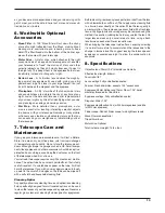
7. Remove the wing nuts and washers from the two screws
of the tube mounting clamp.
8. Now insert the screws into the holes in the equatorial
mount’s saddle plate (
Figure 9A). Then replace the wash-
ers and wing nuts on the screws and tighten them to
secure the mounting clamp (
Figure 9B).
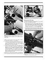
9. Open the mounting clamp and lay the telescope opti-
cal tube in the clamp. Then close the clamp around the
tube and lock it by turning the clamp lock bolt clockwise
and thread it into the clamp’s bottom flange, as shown in
Figure 10.
10. With the tube now secure in the mounting clamp, attach
the red dot finder scope (I) to the optical tube. Do this by
orienting the finder scope as shown in
Figure 11 and slide
the bracket foot back into the finder scope base as far as it
will go.
11. Insert the star diagonal (J) into the focuser drawtube and
tighten the thumbscrew on the drawtube collar. Then insert
the 25mm eyepiece (K) into the diagonal and secure it by
lightly tightening the thumbscrew on the diagonal (
Figure
12).
The telescope is now completely assembled! Before it can be
effectively used, however, there are a couple of things to do to
prepare the telescope for operation.
3. Preparing the Telescope
for Operation
Aligning and Using the Red Dot Finder Scope
The included red dot finder scope (I) makes pointing your tele-
scope almost as easy as pointing your finger! It’s a non-magnify-
ing aiming device that superimposes a tiny LED-illuminated red
dot on the sky, showing exactly where the telescope is pointed. It
permits easy object targeting prior to observation in the higher-
power main telescope.
Before you can use the red dot finder scope, you must remove
the tab sticking out from the battery compartment (
Figure 13).
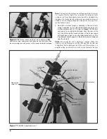
Figure 2
.
The fully assembled BX90 EQ refractor.
L
I
A
B
E
D
H
G
K
J
F
F
C
R.A.
Axis
Dec.
Axis
Summary of Contents for 52588
Page 3: ...3 Figure 1 Parts of the BX90 EQ refractor A H I J F G C D B L K M E...
Page 14: ...14...
Page 15: ...15...


