

Q I G
Quick Installation Guide
Q
uick
I
nstallation
G
uide
Version 1.1
Q I G
Cable Types and Specifications:
For pin assignments for different types of cables, please refer to the following
tables.
10/100 Base-T(X) MDI/MDI-X
Pin Number
MDI port
MDI-X port
1
TD+(transmit)
RD+(receive)
2
TD-(transmit)
RD-(receive)
3
RD+(receive)
TD+(transmit)
4
Not used
Not used
5
Not used
Not used
6
RD-(receive)
TD-(transmit)
7
Not used
Not used
8
Not used
Not used
Note: “+” and “-” signs represent the polarity of the wires that make up each
wire pair.
10/100 Base-T(X) RJ-45
Pin Number
Assignment
1
TD+
2
TD-
3
RD+
4
Not used
5
Not used
6
RD-
7
Not used
8
Not used
Resetting
To restore the switch configurations back to the factory defaults, press the
button for 5 seconds.
Reset
Configurations
After installing the switch, the green power LED should turn on. Please refer to the
following tablet for LED indication.
1. Launch the Internet Explorer and type in IP address of the switch. The default static IP address is
192.168.10.2
Follow the steps to set up the card:
PRINTED ON RECYCLED PAPER
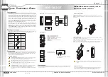
Industrial secure serial port to
Ethernet Device Server
Device
Server
Cable
Type
Max. Length
Connector
10Base-T
Cat. 3, 4, 5 100-ohm
UTP 100 m (328 ft)
RJ-45
100Base-TX
Cat. 5 100-ohm UTP
UTP 100 m (328 ft)
RJ-45
1000Base-T
Cat. 5/Cat 5e 100-ohm UTP
UTP 100 m (328 ft)
RJ-45
1000Base-T RJ-45 port
Pin Number
Assignment
#1
BI_DA+
#2
BI_DA-
#3
BI_DB+
#4
BI_DC+
#5
BI_DC-
#6
BI_DB-
#7
BI_DD+
#8
BI_DD-
1000Base-T RJ-45
Pin Number
MDI port
MDI-X port
1
BI_DA+
BI_DB+
2
BI_DA-
BI_DB-
3
BI_DB+
BI_DA+
4
BI_DC+
BI_DD+
5
BI_DC-
BI_DD-
6
BI_DB-
BI_DA-
7
BI_DD+
BI_DC+
8
BI_DD-
BI_DC-
DB9 serial port
The device can be connected to a serial device using a DB9 cable. The DB9
connector supports RS232 / RS422 / RS485 operation modes. Please refer to the
following table for the pin assignments of the DB9 connector.
Pin #
RS-232
RS-422
RS-485
( 4 wire )
RS-485
( 2 wire )
1
DCD
TX-
TX-
DATA -
2
RXD
TX+
TX+
DATA +
3
TXD
RX+
RX+
4
DTR
RX-
RX-
5
GND
GND
GND
6
DSR
7
RTS
8
CTS
9
RI
1 2 3 4 5
6 7 8 9
DB9 connector
Wiring
The device has two sets of DC power inputs on a 6-pin terminal block
located on bottom of the device. Follow the steps below to wire the
power input on the terminal block.
Power inputs
STEP 1:
Insert the negative/positive wires into the V-/V+ terminals, respectively.
STEP 2:
To keep the wires from pulling loose, use a small flat-blade screwdriver to
tighten the wire-clamp screws on the front of the connector.
PWR-2
PWR-1
V2+ V2- Relay V1+ V1-
LED
Color
Status
Description
PWR1/2
Green
On
Power is on and function normally
Fault
Amber
On
Faulty relay (power failure or port disconnected)
10/100/1000Base-T(X) Ethernet ports
LNK/ACT
Green
On
Port is connected
Green
Blinking
Transmitting data
Speed
Green
On
Port running at 1000Mbps.
Amber
On
Port running at 100Mbps.
Green/ Amber
Off
Port running at 10Mbps.
Serial ports
S1~S4
Red
On
Receiving data
Green
On
Transmitting data
Power
Redundant Input power
Dual DC inputs. 12~48VDC on 6 pin terminal block
Physical Characteristic
Enclosure
IP-30 Aluminum
Dimension (W x D x H)
54.2(W)x 107.1(D)x 145.4(H) mm (2.13x4.22x5.72 inch.)
Weight (g)
Environmental
-40 to 85 C (-40 to 185 F)
o
o
Storage Temperature
5% to 95% Non-condensing
Operating Humidity
-40 to 70 C (-40 to 158 F)
o
o
Operating Temperature
Network Protocol
740g
Power Consumption(Typ.)
6.96W
Overload current protection
Present
Reverse polarity protection
Present on terminal block
Protocol
ICMP, IP, TCP, UDP, DHCP, BOOTP, SSH, DNS, SNMP, V1/V2c, HTTPS
Regulatory Approvals
EN 55032, CISPR32, EN 61000-3-2, EN 61000-3-3, FCC Part 15 B class A
EMI
EN 55024 (IEC/EN 61000-4-2 (ESD), IEC/EN61000-4-3 (RS), IEC/EN61000-4-4 (EFT),
IEC/EN 61000-4-5 (Surge), IEC/EN 61000-4-6 (CS), IEC/EN 61000-4-8(PFMF),
IEC/EN 61000-4-11(DIP))
EMS
IEC60068-2-27
Shock
IEC60068-2-31
IEC60068-2-6
Vibration
Free Fall
MTBF
560362.4721 hrs
EN60950-1
Safety
2. Log in with default user name and password (both are admin). After logging in, you should see the
following screen. For more information on configurations, please refer to the user manual. For
information on operating the device using Oring’s Open-Vision management utility, please go to ORing
website.
RS-232
Flow Control
10/100/1000Base-T(X) Ports in
Auto MDI/MDIX
2
Physical Ports
Technology
Stop Bits
Data Bits
1, 1.5, 2
TxD, RxD, RTS, CTS, DTR, DSR, DCD, RI, GND
XON/XOFF, RTS/CTS, DTR/DSR
7, 8
Serial Ports
Connector
DB9 x 4
Operation Mode
Serial Baud Rate
110 bps to 921.6 Kbps
RS-232/422/485
IDS-342GT
Specifications
ORing Device Server
Model
Parity
odd, even, none, mark, space
Jumbo frame
Up to 9.6K Bytes
CE EMC (EN 55024, EN 55032), FCC Part 15 B
EMC
Warranty
5 years
ORing Industrial Networking Corp.
Copyright© 2015 ORing
All rights reserved.
TEL: +886-2-2218-1066
FAX: +886-2-2218-1014
Website: www.oringnet.com
E-mail: [email protected]
IDS-342GT
IDS-342GT