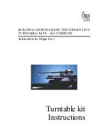
background image


12

Example D

Cantilever struts

Post

Carbon fibre rod

Sub-chassis

Plinth

Example C

Rubber bands 1-10 off

Sub-chassis

Plinth

Example A

Rod

Plinth top plate

Sub-chassis

Spring

Example B

Sub-chassis

Cupped insert

(optional)

Plinth


The sub-chassis design is highly critical for performance. Conceptually the ideal solution is a rigid frame of low resonance 
supported at a point half way between the arm base and platter spindle (this point is ultimately the centre of force 
between the cartridge and bearing). Both the bearing house and arm base should be rigidly decoupled from the sub-
chassis. To achieve this we suggest an open frame of steel angle bar bolted together with Allen bolts - See below (welding 
or gluing does not appear to work well). A sheet of aluminium plate cut with a jig-saw is simpler and can be stiffened by 
bolting on steel angle bar. Whatever your final design, it is recommended that you decouple the arm and bearing house 
by means of plates bolted separately to the main sub-chassis assembly. A bearing plate is supplied with the kit for this 
purpose.  

25 mm Angle bar

Arm board plate

Bearing house plate


If you are using the spring kit please see “Diagram of support bolts and spring arrangement” in the section describing the 
Ultra kit assembly. This shows how the springs are fitted and seat into a sub-chassis. 

Main Bearing attachment 

The main bearing is attached as shown in diagram below or in a similar manner. 

Bearing House

Plinth

De-coupling brass washer

Nut

Bearing plate

Hole 1.5” Dia or larger


Summary of Contents for Turntable kit ALL VERSIONS

Page 1: ...BUILDING OR INSTALLING THE ORIGIN LIVE TURNTABLE KITS ALL VERSIONS Instructions by Origin live Turntable kit Instructions...

Page 2: ...2 V I E W O F U L T R A K I T M I N U S S U B P L A T T E R A N D P L A T T E R V I E W O F A S S E M B L E D U L T R A K I T F R O M U N D E R S I D E...

Page 3: ...e 3 threaded support bolts Error Bookmark not defined Install the sub chassis Error Bookmark not defined Fit Bearing house Error Bookmark not defined Fit the motor Error Bookmark not defined Install S...

Page 4: ...clip connections and mounting 24 Setting up hi fi cartridges 25 Mounting 25 Tracking Force 25 Tangency Alignment 25 Azimuth for experts only 25 Vertical Tracking Angle VTA 26 Antiskate Force pivoting...

Page 5: ...out connections Error Bookmark not defined Diagram of support bolts and spring arrangement Error Bookmark not defined Diagram showing bearing house fastening arrangement Error Bookmark not defined Dia...

Page 6: ...tion will result For example some people expect all bolts to be fully tightened but testing has shown this to have a significant degrading effect in certain situations Building a turntable will be rel...

Page 7: ...shers bearing house plate armboard Lid 2 off Lid hinges 4 off M4 screw M4 nuts Optional parts Ultra plinth 4 off small rubber feet 4 nails Sub chassis MDF damper arm spring plates glued washers Spring...

Page 8: ...proach to cover all eventualities Because of the enormous range of possibilities for the first two of the above three types of installation this section can only cover general principles It is importa...

Page 9: ...m Belt Note Only dimensions marked c are critical All dimensions are in mm 88mm 276mm 326mm 223mm Rega 211mm Linn Mo tor 472mm Switch 123mm c For switch hole first counterbore 1 dia from underside if...

Page 10: ...l dimensions are in mm 88mm 276mm 326mm 223mm Rega 211mm Linn Mo tor 472mm Switch 123mm For switch hole first counterbore 1 dia from underside if necessary to leave 6 mm 1 4 thickness Then drill 9 5 m...

Page 11: ...ed as a one piece non sub chassis design Sub chassis shape plate Can be above or below plinth Plinth shape Non lid example Suggested plinth cross section for suspended subchassis design Suggested heig...

Page 12: ...d together with Allen bolts Seebelow welding or gluing does not appear to work well A sheet of aluminium plate cut with a jig saw is simpler and can be stiffened by bolting on steel angle bar Whatever...

Page 13: ...fitted precision pulley do not move Motor Plinth top plate Motor in elongated hole to allow position adjustment see layout diagrams Screw Motor Plate Wiring The wiring instructions are contained in t...

Page 14: ...agram of lid assembly and rubber feet PLINTH SIDE WALL LID Washer HINGE HINGE SUPPORT HOUSING M4 HINGE BOLTS PLINTH RUBBER FOOT Fit the Lid Fit the hinges onto the lid first using the four M4 bolts an...

Page 15: ...edge of 2 opposite sides of the strip board drill these shallow holes using a 3mm dia drill and screw the board into position with two No 6 x screws and the brass washers such that the washers catch o...

Page 16: ...pplied Note Small ring in thin spring position Spring Rubber Serrated washer Nut to adjust suspension height Install the sub chassis Fit Bearing house Fit the bearing house to the sub chassis as shown...

Page 17: ...ng house Generally the optimum position is such that marker boltin the slot is located at approx the mid point of the slot and this provides a useful reference point Install Sub chassis Fit springs Fi...

Page 18: ...Avoid pulling the external wires at the base of toneamrs as they are not indestructible and can become detached if excessive force is used to manipulate them You can use one hole or two in the rear o...

Page 19: ...speed checks When the rotary switch is turned fully anti clockwise the motor is off One click of the switch clockwise is 33 3 rpm and the second click clockwise is 45rpm Use the strobe card provided...

Page 20: ...or anything other than the dc motor or the power supply will definitely be irreparably damaged and so might the equipment it is connected to Always de power the circuit when troubleshooting by removin...

Page 21: ...earing house try adding a few drops to see if you get overflow keep adding oil till you achieve this Please note that it is not a cause for concern if your Oil has turned black in the bearing house th...

Page 22: ...of Stylus force guage Most stylus force gauges work on the same principle as a set of scales or balances For example with the Ortofon Stylus Force Gauge first place the stylus on the inscribed or gra...

Page 23: ...s and modifications are not guaranteed by Rega so in the event of a warranty claim you should contact ourselves rather than Rega Notes A detailed description of Cartridge set up and care is included i...

Page 24: ...platter bearing performance and the arm s dynamics specifically anti skate are negatively affected So be sure your turntable platter and tonearm mounting board are level use a spirit level If the plat...

Page 25: ...best precaution is to keep the screwdriver well away from the cantilever use a nonferrous screwdriver or keep the stylus guard on when you re using the screwdriver near it The other main hazard is chi...

Page 26: ...pposing balancing force to the natural inward drag of a pivoting arm while playing Left uncontrolled the stylus would push up against the inner groove wall causing distortion both from mistracking and...

Page 27: ...a number of fluids on the market that increase stylus life and help to clean gunge from the needle awordof caution though some of these can loosen the stylus glue on the cantilever over time some flu...

Page 28: ...IGIN LIVE Unit 5 362b Spring Road Sholing Southampton SO19 2PB U K Tel 02380 578877 Fax 02380 578877 Owner Mark Baker C Eng BSc Hons MRINA e mail originlive originlive com web site http www originlive...

Reviews: