7
z
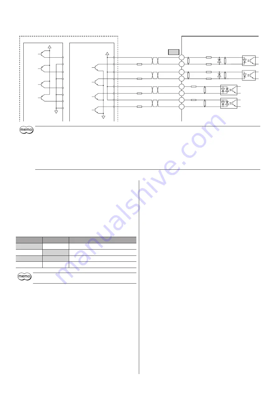
When using the voltage of input signals at 24 VDC
Driver
R1
1.5 to 2.2 kΩ, 0.5 W or more
R1
1.5 to 2.2 kΩ, 0.5 W or more
R2
1.5 to 2.2 kΩ, 0.5 W or more
0 V
0 V
FWD
RVS
AWO
CN3
Twisted pair cable
4
3
2
1
6
5
100 Ω
Current sink output circuit
Current source output circuit
Programmable controller
100 Ω
100 Ω
100 Ω
470 Ω
2.2 kΩ
2.2 kΩ
2.2 kΩ
2.2 kΩ
1 kΩ
M0
8
7
470 Ω
1 kΩ
24 VDC
24 VDC
R2
1.5 to 2.2 kΩ, 0.5 W or more
y
The input voltage specification for the FWD input and RVS input is 5 VDC. If the voltage exceeding 5 VDC is applied, connect an external resistor R1 so
that the input current becomes 7 to 20 mA.
Example) When the 24 VDC is connected: R1=1.5 to 2.2 kΩ, 0.5 W or more
y
The input voltage specification for the AWO input and M0 input is 5 VDC. If the voltage exceeding 5 VDC is applied, connect an external resistor R2 so
that the input current becomes 5 to 15 mA.
Example) When the 24 VDC is connected: R2=1.5 to 2.2 kΩ, 0.5 W or more
y
When an accessory external resistor module
VCS01
is connected instead of the external resistor R1 and R2, use at 24 VDC ±5%.
y
Up to three cables can be used for the connection between the motor and driver. Keep 10 m (32.8 ft.) or less for the wiring distance between the motor
and driver.
Explanation of I/O signals
z
Input signals
All input signals of the driver are photocoupler inputs.
The signal input state represents "ON: Carrying current" or "OFF: Not carrying
current" state of the internal photocoupler rather than the voltage level of the
signal.
•
FWD (Forward) input, RVS (Reverse) input
Turning the FWD input or RVS input ON will start continuous operation.
FWD input
RVS input
Motor movement
ON
OFF
The motor rotates in the forward direction.
OFF
ON
The motor rotates in the reverse direction.
ON
ON
Immediate stop
OFF
OFF
Deceleration stop
If the driver power is turned ON while the FWD input or RVS input is
being ON, the motor will operate.
•
AWO (All windings off) input
When the AWO input is turned ON, the motor current will be cut off and the
motor will lose its holding torque. The motor output shaft can be turned
manually.
When the AWO input is turned OFF, current will be supplied and the holding
torque will be restored.
Also, when the overheat alarm was generated, the alarm can be reset if the
AWO input is turned from OFF to ON after the circuit temperature of the
driver decreased 75 °C (167 °F) or lower.
•
M0 (Data selection) input
Turning the M0 input OFF will select the Speed1 (high speed).
Turning the M0 input ON will select the Speed2 (low speed).
z
Output signals
The driver outputs signals are photocoupler/open-collector output.
The signal output state represents "ON: Carrying current" or "OFF: Not
carrying current" state of the internal photocoupler rather than the voltage
level of the signal.
•
ALM (Alarm) output
The ALM output is normally closed. When an alarm generates, the ALM output
will turn OFF and the motor current will be cut off. At the same time, the PWR/
ALM LED of the driver will blink in red.
•
PLS-OUT (Pulse) output
The PLS-OUT output are output 50 times with each revolution of the motor
output shaft. ON-OFF ratio (duty ratio) for when the motor is operated at
constant speed is 50%.
The maximum output frequency is 500 Hz.


