

4
●
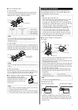
25 to 150 W types
Terminal cover screws
(with rubber seal and
metal washer)
Terminal box cover
Cable outlet of
terminal box
Motor connecting
terminal
Cable clamp
Terminal plinth
Gasket
Gasket
Terminal block
Pressure sealing ring
Rubber packing
Cable
Terminal cover
Cable clamp
•
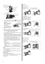
To ensure safety, ground the motor using the
inside the terminal
box. On the three phase round shaft motor type, refer to the following
specification.
Applicable crimp terminal:
Insulated round crimp terminal
Terminal screw size: M4
Tightening torque:
1.0 to 1.3 N·m (8.8 to 11.5 lb-in)
Applicable minimum lead wire
size: AWG18 (0.75 mm
2
) or
more
Ø4.1 (Ø0.161) or more
4.5 (0.177) or less
9 (0.354) or less
Unit [mm (in.)]
•
For wiring, be sure to use cable that meets the following specifications.
Cable: Diameter is Ø6.0 to 12.0 mm (Ø0.236 to 0.472 in.)
Lead Wires: Thickness is AWG24 to 12 (0.2 to 3.5 mm
2
)
Length of strip is 8 mm (0.31 in.)
•
When sealing the terminal cover, ensure that no scraps or particles get
caught between the contact surfaces.
•
The terminal cover screws are specifically designed for mounting the
terminal cover. They are provided with a rubber seal and metal washer
that keep the terminal box splashproof. In order to maintain a tight seal
around the terminal box, use only the provided screws.
Also, this terminal box is constructed to hold a gasket. If this gasket
comes out of the box, please reseal it correctly on the box.
Also refer to the tightening torque table to determine the appropriate
tightening torque to use when fastening the terminal box cover and
cable outlet.
Tightening torque
Terminal Box Cover
0.
3
to 0.
4
N·m (
42
to
56
oz-in.)
Cable Outlet of Terminal Box
Cover
2.5 to 3.8 N·m (350 to 530 oz-in.)
Cable Clamp
0.2 to 0.3 N·m (28 to 42 oz-in.)
Motor Connecting Terminals
0.5 to 0.8 N·m (71 to 113 oz-in.)
Note
To make shielding function fully effective, use a cable of an
appropriate diameter.
Securely affix the cable exposed outside the motor so that it
does not receive stress.
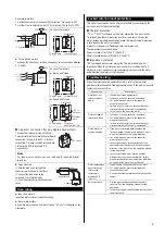
Wiring diagram
Connect the motor according to the figure.
Directions of rotation in the diagram are shown as viewed from the flange
surface of the motor. “CW” indicates clockwise and “CCW”
counterclockwise.
6 W type
●
Single-phase motors
Induction motors
The connection method will vary, depending on the direction.
Clockwise Counterclockwise
CW
Capacitor
L
N
Motor
U1
U2
Z2
Capacitor
CCW
L
N
Motor
U1
U2
Z2
Reversible motors
To rotate the motor in a clockwise
(CW) direction, flip switch to CW.
To rotate it in a counterclockwise
(CCW) direction, flip switch to
CCW.
Layout of terminals
CW
Capacitor
CW
CCW
CCW
N
Motor
U1
U2
Z2
L
Rubber bush
Screw
3-M3.5
U1
U2
Z2
●
Three-phase motors
To change the direction of rotation, change any two connections between
U, V and W.
Layout of terminals
U
V
W
CW
Motor
L1 (R)
L2 (S)
L3 (T)
Rubber bush
Screw
3-M3.5
W
V
U
25 to 150 W type
●
Single-phase motors
Induction motors
The connection method will vary, depending on the direction.
Clockwise
Layout of terminals
CW
Capacitor
L
N
Motor
U1
U2
Z2
PE
Cable clamp
4 terminals
Terminal block
Z2
U2
U1
Counterclockwise
Capacitor
CCW
L
N
Motor
U1
U2
Z2
PE