2
Driver
Connection
Power source connection
The power-supply input voltage is
24VDC-40VDC±10%
. Use a power source that can supply the following current capacity.
Applicable lead wire diameter: AWG26 ~ 16 (0.14 ~ 1.5mm
2
)
Note
• Make the input-signal voltage 5VDC minimum and 24VDC maximum. When
the input-signal voltage is 5VDC, external resistor R
1
is not necessary. If the
input-signal voltage is greater than 5VDC, connect external resistor R
1
, to
restrict the input current as follows:
PLS: 7mA ~ 14mA
DIR./C.OFF: 10mA ~ 14mA
• Use an output-signal voltage of 5VDC minimum and 30VDC maximum, and
use output-signal current of 5mA max. If the output-signal current is greater
than 5mA, connect external resistor R
2
, to restrict the current to no more than
5mA.
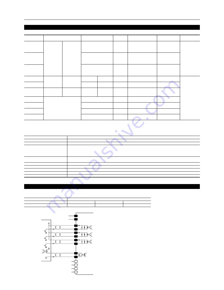
TB3
1
2
3
4
+5V
330
Ω
R
1
R
1
R
1
R
2
330
Ω
330
Ω
24VDC-40VDC
GND
TB2
TB1
1
2
+5V
Controller
STEP input
DIR. input
C.OFF input
TIM. output
1
3
5
7
2
4
6
8
+
-
+
-
+
-
+
-
1k
Ω
1k
Ω
1k
Ω
8 lead wire type
1: Black/Orange
2: Green/Yellow
3: Red/Brown
4: Blue/White
Motor lead wire
4 lead wire type
1: Black
2: Green
3: Red
4: Blue
D2D2043-S
24VDC-40VDC±10% 5.3A
Microstep
Photocoupler input 5VDC, 14mA maximum, Input resistance 330
Ω
Signal voltage
Photocoupler ON: +4.2 ~ +6.0V
Photocoupler OFF: 0 ~ +0.7V
PLS, DIR, C.OFF, RESET
Photocoupler Open-collector output
Excitation monitor, Error: 30VDC maximum, 5mA maximum
Automatic current cutback, Overcurrent protection, Voltage-drop protection, Regenerative protection, Overheat protection
500
Natural ventilation
8.8 (0.25)
+32°F ~ +104°F (0°C ~ +40°C)
Driver model
Power input voltage
Excitation mode
Input signal
Output signal
Function
Maximum response pulse rate
kHz
Driver cooling method
Mass
oz (kg)
Ambient temperature range
• The input-power current supplied to the driver represents the maximum input value (which varies with pulse speed).
Example of connection
∗
1 S: Bipolar series P: Bipolar parallel
∗
2 Specifications for the
PK26
M
• Set the current motor standstill so that it will be a maximum of 50% of the motor’s running current.
Motor model
PK264-E2.0A
PK264M-E2.0A
PK264-E2.0B
PK264M-E2.0B
PK266-E2.0A
PK266M-E2.0A
PK266-E2.0B
PK266M-E2.0B
PK268-E2.0A
PK268M-E2.0A
PK268-E2.0B
PK268M-E2.0B
PK296-F4.5A
PK296-F4.5B
PK299-F4.5A
PK299-F4.5B
PK2913-F4.0A
PK2913-F4.0B
PV264-D2.8AA
PV264-D2.8BA
PV266-D2.8AA
PV266-D2.8BA
PV267-D2.8AA
PV267-D2.8BA
PV269-D2.8AA
PV269-D2.8BA
Rated current
∗
1 A/phase
Motor running current adjustment
Maximum holding torque
∗
1
oz-in (N·m)
75 (0.55)
170 (1.25)
270 (1.9)
150 (1.06)
248 (1.75)
312 (2.2)
440 (3.1)
Voltage
∗
1
VDC
S: 4.0
P: 2.0
S: 5.1
P: 2.6
S: 6.4
P: 3.2
S: 2.8
P: 1.4
S: 3.9
P: 1.9
S: 5.3
P: 2.6
2.1
2.8
3.4
4.2
Resistance per phase
∗
1
Ω
/phase
S: 2.8
P: 0.7
S: 3.6
P: 0.9
S: 4.5
P: 1.13
S: 0.96
P: 0.24
S: 1.32
P: 0.33
S: 1.94
P: 0.49
0.73
1
1.2
1.49
Rotor inertia
oz-in
2
(kg·m
2
)
0.657 (120 × 10
-7
)
1.65 (300× 10
-7
)
2.63 (480× 10
-7
)
7.66 (1400 × 10
-7
)
14.8 (2700 × 10
-7
)
21.9 (4000 × 10
-7
)
1.54 (280 × 10
-7
)
2.47 (450 × 10
-7
)
3.12 (570 × 10
-7
)
4.93 (900 × 10
-7
)
Basic step angle
deg
1.8 [0.9]
∗
2
1.8
2.8
Switch 2: ON
RUN: 4
P: 2.8
Switch 2: ON
RUN: 4
P: 4.38
Switch 2: ON
RUN: F
P: 4.38
Switch 2: ON
RUN: F
S: 1.4
Switch 2: OFF
RUN: A
S: 3.1
Switch 2: ON
RUN: 6
S: 2.8
Switch 2: ON
RUN: 4
S: 420 (3.0)
S: 850 (6.0)
S: 1320 (9.3)
P: 290 (2.1)
P: 600 (4.2)
P: 900 (6.4)
Main specifications
Motor (specifications of applicable motor)
Driver model
Motor type
Power-supply current capacity
PK26
type
2.7A minimum
D2D2043-S
PV26
type
3.2A minimum
PK29
type
5.3A minimum


