2
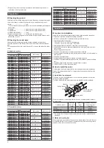
Model
Motor model
Capacitor model
Combination type
Pinion shaft type
5RK60AW-
J
5RK60GVH-AWJ
5RK60GVH-AW
CH250CFAUL2
5RK60AW-
U
5RK60GVH-AWU
CH200CFAUL2
5RK60CW-
J
5RK60GVH-CWJ
5RK60GVH-CW
CH60BFAUL
5RK60CW-
E
5RK60GVH-CWE
CH50BFAUL
5RK90AW-
J
5RK90GVR-AWJ
5RK90GVR-AW
CH350CFAUL2
5RK90AW-
U
5RK90GVR-AWU
CH300CFAUL2
5RK90CW-
J
5RK90GVR-CWJ
5RK90GVR-CW
CH80BFAUL
5RK90CW2-
E
5RK90GVR-CW2E
5RK90GVR-CW2 CH70BFAUL
Installation
Location for installation
Install it in a well-ventilated location that provides easy access for inspection.
The location must also satisfy the following conditions:
z
•
Inside an enclosure that is installed indoors (provide vent holes)
z
•
Operating ambient temperature
−10 to +40 °C (+14 to +104 °F) (non-freezing)
−10 to +50 °C (+14 to +122 °F) for 100 V/200 V
z
•
Operating ambient humidity 85%, maximum (non-condensing)
z
•
Area that is free from an explosive atmosphere or toxic gas (such as sulfuric
gas) or liquid
z
•
Area not exposed to direct sun
z
•
Area free of excessive amount dust, iron particles or the like
z
•
Area not subject to splashing water (storms, water droplets), oil (oil droplets) or
other liquids
z
•
Area free of excessive salt
z
•
Area not subject to continuous vibration or excessive shocks
z
•
Area free of excessive electromagnetic noise (from welders, power machinery,
etc.)
z
•
Area free of radioactive materials, magnetic fields or vacuum
z
•
1000 m (3300 ft.) or less above sea level
How to install the motor
For the pinion shaft type, assemble the motor and gearhead (sold separately).
Refer to "Installing the gearhead" on 3 page about how to assemble the motor
and gearhead.
z
z
Installation to equipment
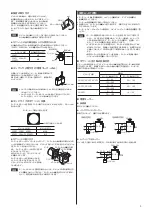
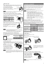
Drill holes on the mounting plate and fix the motor and gearhead on the plate
using four screws (provided).
For pinion shaft type, the mounting screws are provided with the gearhead.
Motor
Screw provided
with gearhead
Gearhead
Mounting plate
Washer
Nut
Spring Washer
Maximum thickness of mounting plate for the case of using provided screws is
as below chart.
Gearhead model
∗
Nominal
diameter of
screw
Tightening
torque
[N·m (lb-in)]
Maximum thickness
of mounting plate t
[mm (in.)]
2GV
M4
1.8 (15.9)
5 (0.20)
3GV
,
4GV
M6
6.4 (56)
8 (0.31)
5GV
,
5GVH
,
5GVR
M8
15.5 (137)
12 (0.47)
z
∗
The square box in the gearhead model will contain a value representing the
gear ratio.
z
z
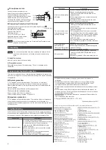
Motor with cooling fan
When installing a motor with cooling fan onto a device, leave 10 mm (0.39 in.) or
more behind the fan cover or open a ventilation hole so that the cooling inlet on
the back of the motor cover is not blocked.
z
•
Dispose the product correctly in accordance with laws and regulations, or
instructions of local governments.
Preparation
Checking the product
Verify that the items listed below are included. Report any missing or damaged
items to the branch or sales office from which you purchased the product.
z
•
Motor ......................................1 unit
(The combination type comes with the motor and its dedicated gearhead pre-
assembled.)
z
•
Capacitor ................................1 piece (only for single-phase motors)
z
•
Capacitor cap .........................1 piece (only for single-phase motors)
z
•
OPERATING MANUAL ...........1 copy
z
•
Set of mounting screws ..........1 set (only for combination type)
(Mounting screws, hexagonal nuts, washers, spring washers 4 pieces each,
parallel key 1 piece)
Checking the model name
Check the model number against the number indicated on the product.
Enter the gear ratio in the box (
) within the model name of the combination
type.
For the speed control motor, enter the code “
R
” in the box (
) within the model
name.
z
z
Induction motors
Model
Motor model
Capacitor model
Combination type
Pinion shaft type
2IK6
AW-
J
2IK6
GV-AWJ
2IK6
GV-AW
CH35FAUL2
2IK6
AW-
U
2IK6
GV-AWU
CH25FAUL2
2IK6
CW-
J
2IK6
GV-CWJ
2IK6
GV-CW
CH08BFAUL
2IK6
CW-
E
2IK6
GV-CWE
CH06BFAUL
3IK15
AW-
J
3IK15
GV-AWJ
3IK15
GV-AW
CH55FAUL2
3IK15
AW-
U
3IK15
GV-AWU
CH45FAUL2
3IK15
CW-
J
3IK15
GV-CWJ
3IK15
GV-CW
CH15BFAUL
3IK15
CW-
E
3IK15
GV-CWE
CH10BFAUL
4IK25
AW-
J
4IK25
GV-AWJ
4IK25
GV-AW
CH80CFAUL2
4IK25
AW-
U
4IK25
GV-AWU
CH65CFAUL2
4IK25
CW-
J
4IK25
GV-CWJ
4IK25
GV-CW
CH20BFAUL
4IK25
CW-
E
4IK25
GV-CWE
CH15BFAUL
5IK40
AW-
J
5IK40
GV-AWJ
5IK40
GV-AW
CH110CFAUL2
5IK40
AW-
U
5IK40
GV-AWU
CH90CFAUL2
5IK40
CW-
J
5IK40
GV-CWJ
5IK40
GV-CW
CH30BFAUL
5IK40
CW-
E
5IK40
GV-CWE
CH23BFAUL
5IK60AW-
J
5IK60GVH-AWJ
5IK60GVH-AW
CH200CFAUL2
5IK60AW-
U
5IK60GVH-AWU
CH180CFAUL2
5IK60CW-
J
5IK60GVH-CWJ
5IK60GVH-CW
CH50BFAUL
5IK60CW-
E
5IK60GVH-CWE
CH40BFAUL
5IK90AW-
J
5IK90GVR-AWJ
5IK90GVR-AW
CH280CFAUL2
5IK90AW-
U
5IK90GVR-AWU
CH250CFAUL2
5IK90CW-
J
5IK90GVR-CWJ
5IK90GVR-CW
CH70BFAUL
5IK90CW-
E
5IK90GVR-CWE
CH60BFAUL
4IK25SW-
4IK25GV-SW
4IK25GV-SW
−
5IK40SW-
5IK40GV-SW
5IK40GV-SW
−
5IK60SW-
5IK60GVH-SW
5IK60GVH-SW
−
5IK90SW-
5IK90GVR-SW
5IK90GVR-SW
−
z
z
Reversible motors
Model
Motor model
Capacitor model
Combination type
Pinion shaft type
2RK6
AW-
J
2RK6
GV-AWJ
2RK6
GV-AW
CH45FAUL2
2RK6
AW-
U
2RK6
GV-AWU
CH35FAUL2
2RK6
CW-
J
2RK6
GV-CWJ
2RK6
GV-CW
CH10BFAUL
2RK6
CW-
E
2RK6
GV-CWE
CH08BFAUL
3RK15
AW-
J
3RK15
GV-AWJ
3RK15
GV-AW
CH75CFAUL2
3RK15
AW-
U
3RK15
GV-AWU
CH60CFAUL2
3RK15
CW-
J
3RK15
GV-CWJ
3RK15
GV-CW
CH18BFAUL
3RK15
CW-
E
3RK15
GV-CWE
CH15BFAUL
4RK25
AW-
J
4RK25
GV-AWJ
4RK25
GV-AW
CH100CFAUL2
4RK25
AW-
U
4RK25
GV-AWU
CH80CFAUL2
4RK25
CW-
J
4RK25
GV-CWJ
4RK25
GV-CW
CH30BFAUL
4RK25
CW-
E
4RK25
GV-CWE
CH25BFAUL
5RK40
AW-
J
5RK40
GV-AWJ
5RK40
GV-AW
CH160CFAUL2
5RK40
AW-
U
5RK40
GV-AWU
CH120CFAUL2
5RK40
CW-
J
5RK40
GV-CWJ
5RK40
GV-CW
CH40BFAUL
5RK40
CW-
E
5RK40
GV-CWE
CH35BFAUL

