


8
EN
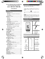
SET UP BASE STATION
NOTE
Install batteries in the remote sensor before the
base station matching the polarities (+ and -).
For continuous use, please install the AC adapter. The
batteries are for back-up use only.
NOTE
Make sure the adapter is not obstructed and is
easily accessible to the unit.
NOTE
The base station and adapter should not be
exposed to wet conditions. No objects filled with liquid,
such as vases, should be placed on the base station
and adapter.
Install the base station batteries (4 x UM-3 / AA) matching
the
polarity + and -. Press
RESET
after each battery
change.
NOTE
Do not use rechargeable batteries. It is
recommended that you use alkaline batteries with this
product for longer performance.
NOTE
Batteries should not be exposed to excessive
heat such as sunshine or fire.
The battery icon indicator
may appear in the
following areas:
AREA
MEANING
Weather Forecast Area
Battery in the base station is
low. will show when AC
adapter is disconnected.
Temperature / Heat
Index / Wind Chill Area
The displayed channel
indicates the outdoor
sensor for which battery
is low.
Wind Speed / Wind
Direction Area
Battery in the wind
sensor is low.
UVI / Barometer /
Rainfall Area
Battery in the UV / Rain
sensor is low.
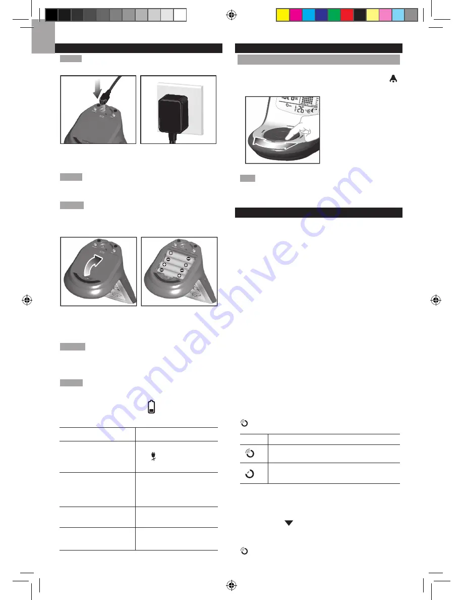
BASE STATION
CHANGE DISPLAY / SETTING
To change the display and settings, use the following
buttons on the rotating dial:
SELECT
,
MEMORY /
ON / OFF
,
MODE
and
ALARM
.
In addition, the
UNIT
and
SEARCH
buttons
located at the bottom
of the base station
allows pre-setting of
the remote sensor
channels and the
measurement units for
display.
TIP
To exit from the setting mode, push any button.
Alternatively, the base station will automatically exit after
30 seconds.
CLOCK RECEPTION
This product is designed to synchronize its calendar
clock automatically once it is brought within range of a
radio signal:
WMR100N:
• EU: DCF-77 signal: within 1500 km (932 miles) of
Frankfurt, Germany.
• UK: MSF-60 signal: within 1500 km (932 miles) of
Anthorn, England.
WMR100NA:
• WWVB-60 signal: within 3200km (2000 miles) of Fort
Collins Colorado.
WMR100N only - slide the
EU
/
UK
switch to the
appropriate setting based on your location. Press
RESET
whenever you change the selected setting.
The reception icon will blink when it is searching for a
signal. If the radio signal is weak it can take up to 24
hours to get a valid signal reception.
indicates the status of the clock reception signal.
ICON
MEANING
Time is synchronized. Receiving signal is
strong
Time is not synchronized. Receiving signal
is weak
To enable (and force a signal search) / disable the
clock radio reception (clock synchronization):
1. Press
SELECT
to navigate to the Clock / Calendar /
Alarm Area.
will show next to the Area.
2. Press and hold
SEARCH
.
appears when it is enabled.


