background image

EN

8

When the remote unit receives the radio-controlled
clock signal and is paired up with the main unit, the
clock in the main unit will automatically be updated.

RADIO SIGNAL

REMOTE SENSOR SEARCHING

The 

RADIO SIGNAL FORMAT

 switch is located

inside the battery compartment. Select EU (DCF)
or UK (MSF). Press 

RESET

.

Reception takes 2 - 10 minutes to complete. Once
complete, the icon will stop blinking.
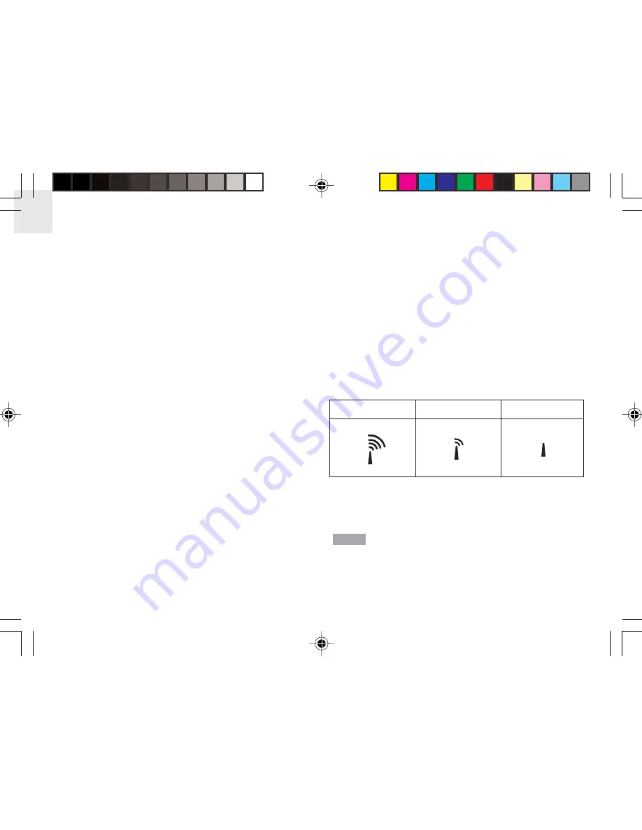
Strong signal

Weak signal

No signal

Press 

SEARCH 

to manually activate search for radio-

controlled clock signal. The tower icon will blink until the
clock signal is found or the search period times out.

The remote unit collects RF signals. For best

results, place it away from metallic or electrical
objects, and in a location with a clear view to the sky.

NOTE

INSTALLATION

Mount the remote unit on a flat surface using the
recess holes on the back of the unit.

For best results:

Insert the batteries and select the measurement
unit and channel number first.

Place the unit out of direct sunlight and
moisture.

Do not place the remote unit more than
50 meters (164 feet) from the main (indoor)
unit.

Position the unit so that it faces the main
(indoor) unit. Minimize obstructions such as
doors, walls, and furniture.

To maximize radio frequency reception for the
radio-controlled clock, place the remote unit in a
location with a clear view to the sky.

You may need to experiment with various locations to
get the best reception.

CLOCK

This remote unit can automatically synchronize the
date and time with official time-keeping organizations
in Frankfurt (Germany) and Rugby (England). When
the unit is within 1500 km (932 miles) of a RF signal,
the reception icon will blink during reception.

AWS888N_En_R2

8/16/04, 4:28 PM

8

Summary of Contents for Color Weather Station AWS888N

Page 1: ...rm mode 13 Turning alarm on off 13 Weather forecast mode 13 Temperature pressure hygro mode 14 Barometer display 14 Thermo hygro memory 14 Clear MIN MAX records 15 Current thermo hygro display 15 Auto...

Page 2: ...duct It contains practical step by step instructions as well as technical specifications and warnings you should know In this box you will find Main unit Remote sensor Batteries AC adaptor PRODUCT OVE...

Page 3: ...3 EN FRONT VIEW 1 Colour display 2 Increase decrease setting 3 ENTER select option BACK VIEW BATTERY COMPARTMENT 1 RESET 2 SEARCH 1 2 3 1 2 AWS888N_En_R2 8 16 04 4 28 PM 3...

Page 4: ...not include the RF function such as THGR228N THGR238N 3 channel sensor THGR328N 5 channel sensor NOTE LCD DISPLAY HOME MENU 1 Weather Forecast Display Mode 2 Clock Alarm Display Mode 3 Temperature Pr...

Page 5: ...status indicator 3 Ventilation duct 1 2 3 LCD 1 RF clock reception 2 Channel no 3 Low battery indicator 4 Time 5 Temperature C or F 6 Relative humidity 7 Temperature Humidity reading 1 2 3 5 6 4 7 AW...

Page 6: ...ount recess hole 2 CHANNEL switch 3 RESET 4 C F switch 5 SEARCH button 6 EU UK radio signal format switch 7 Battery compartment 8 Fold out stand FOLD OUT STAND 1 Fold out the stand 2 Lock it into plac...

Page 7: ...C adaptor should power the main unit NOTE REMOTE UNIT SET UP Up to 5 remote units can be used with this product to monitor outdoor temperature and humidity The remote unit included in this package is...

Page 8: ...OTE INSTALLATION Mount the remote unit on a flat surface using the recess holes on the back of the unit For best results Insert the batteries and select the measurement unit and channel number first P...

Page 9: ...y start when the main unit is reset GENERAL SETTINGS MODE All settings and display options for this product are accessible from the MAIN MENU NAVIGATING THROUGH MAIN MENU To access MAIN MENU from any...

Page 10: ...4 hour format and Analog Digital or Classic Clock display format RF CLOCK Set Auto synchronization on or off 2nd ZONE OFFSET Set 2nd zone time Exit Return to previous page Press to choose a setting th...

Page 11: ...be swinging Press ENTER begin adjusting values Press change values Press ENTER to confirm changes A will indicate that an alarm is active ALARM TYPES DAILY AND WEEKDAYS ALARM DAILY alarm can be set to...

Page 12: ...SETTING mode Temperature Select C or F temperature units Barometric Unit Select Mb hPa or inHg pressure units Altitude Set the compensated altitude 100m to 2500m default 0m Exit Return to previous pag...

Page 13: ...separately without going into the setting mode 1 Press CHANNEL to select alarm 1 or 2 2 Press to switch alarm on or off 3 Press ENTER or wait 10 seconds to confirm the changes TIP You can change the...

Page 14: ...el sensors To display a MIN MAX reading select a channel by pressing CHANNEL 1 1 hour ago 3 3 hours ago 6 6 hours ago 12 12 hours ago 24 24 hours ago The weather forecast symbol is updated every 15 mi...

Page 15: ...y for each channel will be displayed for 4 seconds before changing to the next channel To start auto scan press and hold CHANNEL until you hear a beep press CHANNEL again to exit auto scan mode COMFOR...

Page 16: ...The display turns on when the alarm goes off or a button is pressed AUTO ROTATION DISPLAY MODE When this function is enabled the unit will automatically switch between the following modes Weather for...

Page 17: ...radio frequency link with remote unit or automatic clock etc After resetting the system all system information will be erased and returned to factory defaults The main unit will also check battery con...

Page 18: ...ice if handled properly Observe the following guidelines Never immerse the unit in water This can cause electrical shock and damage the unit Do not subject the main unit to extreme force shock or fluc...

Page 19: ...readings SPECIFICATIONS Main unit dimensions L x W x H 165 x 124 x 39mm 6 5 x 4 88 x 1 54 inches Weight 432g with batteries Remote unit dimensions L x W x H 70 x 24 5 x 116mm 2 76 x 0 96 x 4 57 inche...

Page 20: ...if you d like to contact the Oregon Scientific Customer Care department directly please visit www2 oregonscientific com service support OR call 949 608 2848 in the US For international enquiries plea...

Page 21: ...atibility Article 3 1 b of the R TTE Directive Applied Standards ETSI EN 301 489 1 3 Ver 1 4 1 2002 08 Efficient use of radio frequency spectrum Article 3 2 of the R TTE Directive Applied Standards ET...

Reviews: