background image

5

2. Commissioning and checklist 

Commissioning by Orcon


Orcon is happy to assist you in commissioning the WTU. After the installation has been 
approved  by  Orcon,  you  will  receive  an  additional  one-year  warranty.  Prior  to 
commissioning and in the event of a malfunction, you should check the following points.


Check the installation for the following points:


The WTU and all external equipment have been installed in 
accordance with the installation instructions (see pages 10 to 12).


The cables of the WTU are correctly connected (see pages13to 15).


The WTU is powered and earthed.


The power cables have the correct diameter.


An isolating switch is fitted.


The outside air and exhaust air ducts are insulated.


The silencers are installed and the duct system is correctly 
connected to the WTU.


The diameter of the air ducts must be equal to or larger than the 
connection flanges of the WTU.


The air filters are clean and the air flow is not blocked.


The outside air intake is located at a sufficient distance from 
contaminated air (kitchen exhaust, boiler and fireplaces, etc.).


There is enough space to carry out servicing. Check that the heat 
exchanger, filters and motors (via the side and bottom hatches) are 
accessible and can be replaced if necessary.


Only for the TA series:


A condensate drain is connected to the unit and that it is not 
blocked. Make sure that the reinforced hose is placed at an 
angle.


A CBRF preheater is installed.


Check whether the following data are available (or possibly set):


A weekly schedule with the set normal and reduced fan 
speeds.


Any desired configurations, such as temperature control 
functions, fan control, external control functions, etc., can be 

Summary of Contents for WTU-1000-EC-E

Page 1: ...Installation and user manual WTU EC E IE TA Heat recovery unit with EC motors Regin controller and external display...

Page 2: ...2...

Page 3: ...series 7 Installation 8 Connecting accessories 9 Display Installation of the operating display Explanation Control display Running through menus Start settings Changing access rights Changing operatin...

Page 4: ...of power Install the WTU in an environment where the temperature is between 10 and 40 degrees Celsius and the relative humidity is less than 60 If condensation occurs preheat the fresh air with a CBR...

Page 5: ...d the duct system is correctly connected to the WTU The diameter of the air ducts must be equal to or larger than the connection flanges of the WTU The air filters are clean and the air flow is not bl...

Page 6: ...6 carried out...

Page 7: ...73 76 75 75 Nominal flow rate 100Pa m3 h 200 440 800 1000 1200 1700 Maximum flow rate 0Pa m3 h 374 760 921 1425 2280 2780 Electrical input power at nominal air volume W 44 97 244 256 351 462 SFPint 1...

Page 8: ...E 922 1130 344 200 499 700 46 WTU 800 EC E 1014 1214 410 250 589 760 51 WTU 1000 EC E 1294 1606 410 300 719 760 79 WTU 1500 EC E 1128 1807 552 355 623 800 97 WTU 2000 EC E 1428 1807 552 355 921 800 1...

Page 9: ...ncy 1 82 82 82 Nominal flow rate 100Pa m3 h 500 750 1000 Maximum nominal 0 Pa m3 h 760 869 1288 Electrical input power at nominal air volume W 144 242 277 SFPint 1 W m3 s 7 4 9 6 7 0 Design flow rate...

Page 10: ...are in millimetres The space needed to carry out maintenance is indicated by size S A B C D E S Weight kg WTU 600 EC TA 934 1325 355 200 499 700 64 WTU 800 EC TA 1024 1387 400 250 589 760 71 WTU 1000...

Page 11: ...lles as far apart as possible so that the entire room is ventilated Place control valves in the ducts if multiple extraction grilles are installed All electrotechnical operations and connections must...

Page 12: ...es can be attached to the housing of the WTU by using the using the same screws and the existing screw holes Prepare the threaded endsInstallation of the WTU Hang the WTU with the suspension brackets...

Page 13: ...e system see diagram below Then fit the condensation drain hose into the hose connection the condensation drain must not be kinked Pour water into the drip tray to create a water trap and also check t...

Page 14: ...red wire 24V to terminal 5 and connect the black wire GND to terminal 3 AGND of the WTU terminal strip After connecting the CO2 sensor it must be configured in the controller see page21 Connecting MTV...

Page 15: ...of the controller The temperature sensor supply air temperature sensor connected to AI4 must first be disconnected from AI4 The AGND already connected on the controller should remain the new sensor s...

Page 16: ...16 Note The connections shown in a box are optional Electrical Connections WTU EC E IE TA...

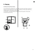
Page 17: ...able connected to the Regin controller If required the 10m cable can be replaced by a cable up to 100m long Determine a suitable place for mounting the control panel control panel If necessary drill t...

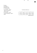
Page 18: ...iption 1 Mounting holes 2 Terminal block 3 Connection brown cable 4 Connection yellow cable 5 Connection white cable 6 Connection black cable Control panel dimensions Dimensions in mm A B C D E 115 94...

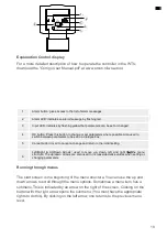
Page 19: ...to do this By clicking on the left arrow one returns to the previous menu level Posit ion Statement 1 Alarm button gives access to the list of alarm messages 2 Alarm LED indicates an alarm message by...

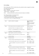
Page 20: ...r temperature see the Return air temp explanation Return air temperature below Measured C This is 21 C as standard log on to service level Desired 21 C code 2222 to change default setting Step 3 Check...

Page 21: ...ay speed must be ventilated There can be 2 periods per Per 1 00 00 24 00 day Per 2 00 00 00 00 d Set the weekend and holiday schedule with the Half turns periods when the WTU is running at reduced spe...

Page 22: ...cess rights Changing access rights By default the WTU is operated with the rights of Operator If you want to make some changes you have to log in as Service or Admin To do this go to Access rights Log...

Page 23: ...0 min run Step7Press the down arrow to set the ppm values 1 2 turn 0ppm 1 1 speed 2000ppm Difference 30ppm Step8Set the rotation speeds for the supply and exhaust fan TV and AV to reduced 15 and norm...

Page 24: ...connected it must be configured as follows Step1Log in as Admin code 1111 Step2Go to Configuration Inputs Outputs Analogue inputs AI3 Press OK Step3Change not used to CO2 Step4Go back to the Configur...

Page 25: ...s Analogue outputs Go to AO3 Change not used to Y1 heating Return to the Configuration menu Click on the down arrow and go to the Heating menu Change Not used to Electric Return to the Configuration m...

Page 26: ...dmin code 1111 Step 2 Go to Configuration Z N ventilation ZNV active No Step 3 Change No to Yes Summer night ventilation will only be activated if the following starting conditions are met Less than 4...

Page 27: ...rn air temperature is below the set value e g 18 C One of the timer outputs for normal speed external stop or extended running time normal is on If the outside temperature falls below a selected value...

Page 28: ...ded from www orcon nl wtu etool The following describes how to connect the controller to a laptop and how to change some settings in the controller To program the WTU the laptop must be connected to t...

Page 29: ...this controller and press Search as shown in Figure 4 Figure 3 First select and then press OK as shown in Figure 5 Press OK as shown in Figure 6 The controller is now connected The status display on t...

Page 30: ...n synchronise as shown in Figure 7 above The synchronise parameters menu will appear 2 Click on Update Tool to make the changes in the controller 3 Enter the administrator password 1111 to change the...

Page 31: ...30 Configuring parameters Figure 9 Click on Configuration as shown in Figure 9 The System menu will appear Figure 10...

Page 32: ...e left side of Figure 10 The Input Output menu will now appear on the right side of the screen 2 By clicking on one of the possible inputs or outputs a drop down menu appears on the far right A choice...

Page 33: ...on the Figure 11 The Rule functions menu appears on the right hand side of the screen 2 Click on Heater type under Object types a selection menu will appear Choose the desired reheater from this menu...

Page 34: ...above The synchronise parameters menu will appear 2 Select the changes you want to make from the synchronise parameters menu 3 Click on update controller to make the changes to the controller 4 Now e...

Page 35: ...k that the fuses are not defective Check the control panel settings times week schedule automatic manual operation etc 2 Reduced airflow Check the settings for the ventilation modes Normal and Reduced...

Page 36: ...nger Step 2 Replace the filters Step 3 Remove the heat exchanger and clean if necessary with a hoover Supply and return air fans The fans have EC controlled external rotor motors that can be steplessl...

Page 37: ...observe these maintenance intervals and to follow the maintenance instructions Thorough and regular maintenance is a prerequisite for a valid warranty 1 Or in accordance with local laws and regulation...

Page 38: ...800 EC E IE 15723080 157230 87 WTU 800 EC TA 15723580 157230 87 WTU 1000 EC E IE 15723100 157231 07 WTU 1000 EC TA 15723600 157231 07 WTU 1500 EC E IE 15723150 157231 57 WTU 2000 EC E IE 15723200 157...

Page 39: ...nd must be replaced Thanks to a back up capacitor the controller will continue to operate for at least 10 minutes even without supply voltage Please leave battery replacement to qualified service pers...

Page 40: ...n the making available on the market of electrical equipment Directive 2014 30 EU on electromagnetic compatibility Regulation EU No 1369 2017 on energy labelling Regulation EU No 1253 2014 Directive 2...

Page 41: ...40 Notes...

Page 42: ...41 Landjuweel 25 3905 PE Veenendaal PO Box 416 3900 AK Veenendaal t 31 0 318 54 47 00 service orcon nl www orcon nl Misprints and printing errors excepted 17 03 2021 r1 3876v10...

Reviews: