STEP 07
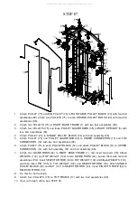
1.
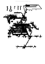
Attach PULLEY (75) and BIG PULLEY (76) to
ROTATABLE PULLEY BLOCK
(33) with two bolt
assemblies (96). Attach two PULLEYS (75) to each
DOUBLE PULLEY BLOCK
(20) with two bolt
assemblies (96).
2.
Attach two PULLEYS (75) to
RIGHT BASE FRAME
(1) with two bolt assemblies (96).
3.
Attach four PULLEYS (75) and three
PULLEY GUARD BARS
(36) to
RIGHT UPRIGHT
(5) with
four bolt assemblies (96).
4.
Attach PULLEY (75) to
SINGLE PULLEY BLOCK
(34) with bolt assembly (96).
5.
Attach PULLEY (75) and
PULLEY GUARD BAS
(36) to
UNDER CONNECTION
(13) and
TOP
CONNECTION
(18) with two bolt assemblies (96).
6.
Attach PULLEY (75) to each
PULLEY BLOCK
(57), and attach
PULLEY BLOCK
(57) to
UPPER
CONNECTION
(14) with bolt assembly (97) and bolt assembly (98).
7.
Attach two
GUIDE RODS
(24) to
RIGHT BASE FRAME
(1), and insert two parts (78), fifteen
WEIGHTS (103) and TOP WEIGHT (102) to two
GUIDE RODS
(24), secure them with two bolt
assemblies (104). Insert
SELECTOR ROD
(30)
to
TOP WEIGHT (102) and fifteen WEIGHTS (103),
and then insert
PIN
(105)
to
TOP WEIGHT (102) and
SELECTOR ROD
(30). Attach
SINGLE
PULLEY BLOCK
(34) and NUT (101) to
SELECTOR ROD
(30). Insert
PIN WITH ROPE
(80) to
SELECTOR ROD
(30).
8.
Do this for both stands.
9.
Attach four PULLEYS (75) to
TOP FRAME
(17) with two bolt assemblies (99).
10.
How to through cable, see STEP 08.
All manuals and user guides at all-guides.com


