


OPTIMOD-AM DIGITAL
INSTALLATION
2-29
D)
Turn on the carrier.
E)
Observe the RF envelope at the common point with a DC-coupled oscilloscope
and advance the
S
QUARE
M
OD
control to produce 30% modulation.
F)
Navigate to
S
ETUP
>
M
ODIFY
S
YS
P
ST
>
TX1/D
AY
.
G)
If necessary, press
N
EXT
until you see the screen containing the four transmit-
ter equalizer controls.
H)
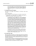
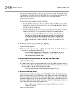
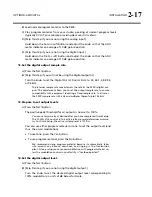
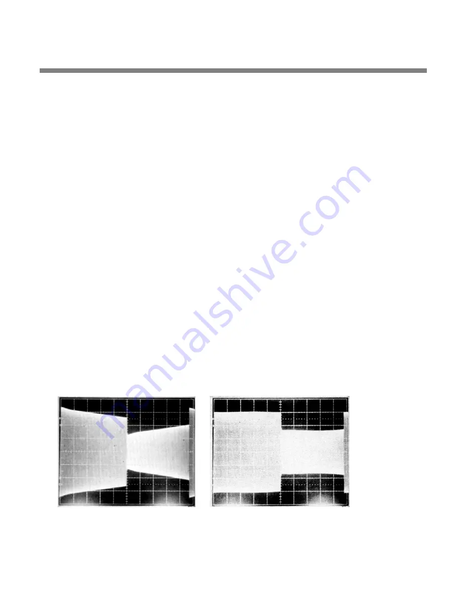
Review the RF envelope display.
Many transmitters (particularly older designs) will produce an RF enve-
lope resembling
. If the oscilloscope display looks like this, con-
tinue to step (I).
If the oscilloscope display looks like
tion is unnecessary. Skip to step 13 on page 2-30.
I)
Set the LF
GAIN
to 10.0 dB.
Setting the LF GAIN control to maximum low-frequency boost ensures re-
sponse that is closest to true DC-coupling, optimizing square wave re-
sponse.
Depending on the transmitter, this large amount of boost at sub-audible
frequencies might cause bounce and/or distortion on heavy bass tran-
sients in music. In step 14 on page 2-32, you will be instructed to turn the
LF
GAIN
control down until these problems are no longer observed. This
will make the measured square wave response poorer. However, engi-
neering realities force a compromise between best small signal (i.e.,
square wave) response and best large signal (i.e., bounce and distortion)
performance. This compromise is best made by careful experimentation
with program material to find the setting of the LF GAIN control that
gives the highest average modulation without audible distortion.
J)
Adjust the
LF
FREQ
to make the square wave as flat as possible.
Work quickly to avoid overheating the transmitter.
shows the
result of a successful adjustment. If a display like that in
could
Figure 2-8: Unequalized RF envelope
(showing tilt)
Figure 2-9: RF envelope requiring
no tilt equalization
Summary of Contents for OPTIMOD-AM 9300
Page 1: ...Operating Manual OPTIMOD AM 9300 Digital Audio Processor Version 2 0 Software...
Page 7: ...Operating Manual OPTIMOD AM 9300 Digital Audio Processor Version 2 0 Software...
Page 178: ...3 46 OPERATION ORBAN MODEL 9300...
Page 200: ......
Page 221: ...OPTIMOD AM DIGITAL TECHNICAL DATA 6 21...
Page 222: ...6 22 TECHNICAL DATA ORBAN MODEL 9300 CONTROL BOARD PARTS LOCATOR...
Page 228: ...6 28 TECHNICAL DATA ORBAN MODEL 9300...
Page 229: ...OPTIMOD AM DIGITAL TECHNICAL DATA 6 29 I O DSP BOARD LEFT AND RIGHT ANALOG INPUTS...
Page 230: ...6 30 TECHNICAL DATA ORBAN MODEL 9300 I O DSP BOARD ANALOG OUTPUTS...
Page 231: ...OPTIMOD AM DIGITAL TECHNICAL DATA 6 31...
Page 238: ...6 38 TECHNICAL DATA ORBAN MODEL 9300 FRONT VIEW REAR VIEW FRONT PANEL PARTS LOCATOR DIAGRAM...