Install the Drive Backplane
d.
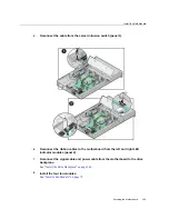
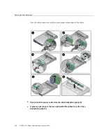
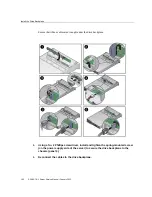
Disconnect the auxiliary signal cable from the drive backplane (panel 4).
4.
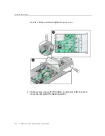
Using a No. 2 Phillips screwdriver, loosen the right-side spring-mounted screw
(on the power supply side of the server) that secures the drive backplane to the
chassis [4].
5.
Lift up on the left-side spring tab, and then gently release the drive backplane
from the standoff hooks and out from under the spring tab (panel 5).
6.
Pull the drive backplane away from the standoff hooks and spring tab and out of
the chassis (panel 6).
7.
Place the drive backplane on an antistatic mat.
8.
Install a drive backplane or continue the service procedure that required aceess.
“Install the Drive Backplane” on page 149
.
Related Information
■
“Internal Component Locations” on page 14
■
“Install the Drive Backplane” on page 149
Install the Drive Backplane
1.
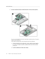
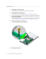
Lower the drive backplane into the server, and then position it under the spring
tab to engage the standoff hooks (panels 1 and 2).
The standoff hooks fit into small openings in the drive backplane.
Servicing the Drive Backplane
149
Summary of Contents for SPARC T8-1
Page 1: ...SPARC T8 1 Server Service Manual Part No E80510 04 January 2022 ...
Page 2: ......
Page 10: ...10 SPARC T8 1 Server Service Manual January 2022 ...
Page 20: ...20 SPARC T8 1 Server Service Manual January 2022 ...
Page 58: ...58 SPARC T8 1 Server Service Manual January 2022 ...
Page 106: ...106 SPARC T8 1 Server Service Manual January 2022 ...
Page 112: ...112 SPARC T8 1 Server Service Manual January 2022 ...
Page 128: ...128 SPARC T8 1 Server Service Manual January 2022 ...
Page 146: ...146 SPARC T8 1 Server Service Manual January 2022 ...
Page 152: ...152 SPARC T8 1 Server Service Manual January 2022 ...

