Welcome Letter Rev 6
3
Locate and Install The Display
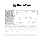
The display will get its “control buttons” mounted
around it. These are typically engraved pistons
with no lamps. If Walker pistons are used and
they are being plugged into the display board,
negative output is required for these particular
pistons.
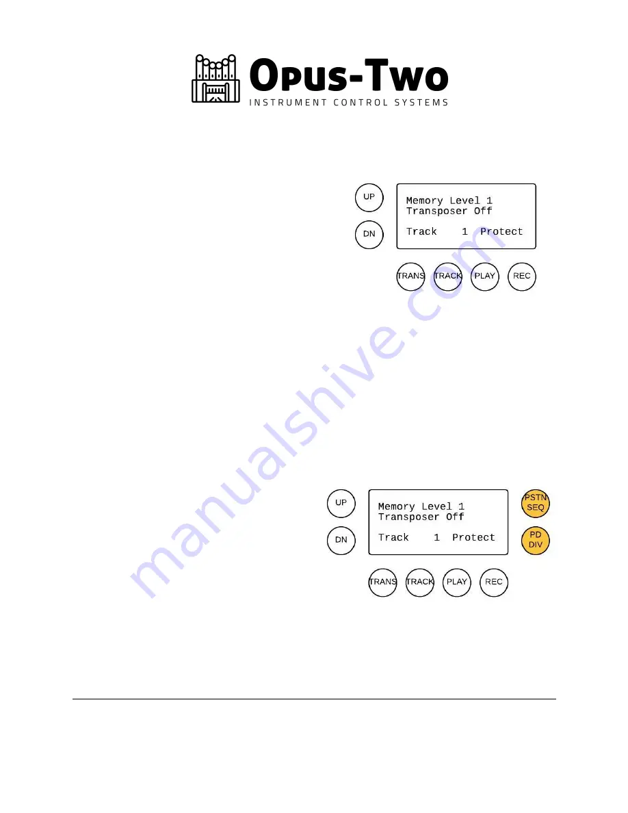
The pistons shown on the drawing at right are
connected to the back of the display. No other
pistons are connected there. See the CVE/CVA
wiring diagram for more information in your wiring guide.
Generally, the pistons should be arranged as shown in the drawing. This allows the easiest
interface and takes into account various buttons that must be pressed together. As tempting as
it may be to integrate the various buttons in piston slips, this makes the control system
extremely frustrating to use. Separate (additional) pistons can be integrated into piston slips,
such as “Mem Up” , “Mem Dn” , “Track Up” , “Track Dn” , “Tra” , “Transpose -” , or any
combination of the above. Piston sequence buttons (previous and next) are also typically in the
piston slips and not with the display.
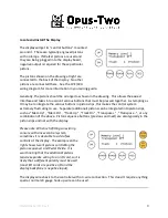
Please note: When retrofitting an existing
console with a new control system,
sometimes it is desirable to add a few
controls at the display. The example on the
right shows two lit pistons controlling the
piston sequencer and Pedal Divide. It is
worth noting that the additional pistons
require separate wiring to an I/O card, so it is
likely that a different polarity must be used
(most I/O cards are positive I/O and the
display backplane is negative input).
The display wires back to the controller with a 3-wire connection. This doesn’t require anything
special, normal 24 gauge hook up wire can be used.


