background image

Delta Elec. Inc. 

ES522 & EX532 


Company Confidential             Optoma___________________            Delta________________ 
55 

2009/06/30


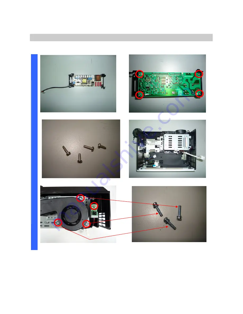
Removing the Ballast & Fan & IR sensor board 


Review the top side of Ballast. 

Remove the four screws. 


Review the four screws (S15). 

Review the bottom side w/o Ballast. 


S

A

E

M

B

L

Remove the four screw. 

Review the three screws (S16). 


Summary of Contents for DP-2400

Page 1: ...Delta Elec Inc ES522 EX532 Company Confidential Optoma___________________ Delta________________ 1 2009 06 30 DATA PROJECTOR ES522 DP 2400 EX532 DP 3400 SERVICE MANUAL...

Page 2: ...iew and LEDs 12 2 10 Optical Adjustment Image Size ES 520 13 2 11 Optical Adjustment Image Size EX 532 14 2 12 BLOCK DIAGRAM 16 2 13 Wire diagram 17 3 TROUBLE SHOOTING 18 4 DISASSEMBLY AND ASSEMBLY ES...

Page 3: ...cription 98 10 2 Power READY LED Blink Code Message 99 10 3 Factory Preset Display Modes 100 11 RS 232 Command 102 12 EDID 106 13 Spare Part List 122 Update History No Description Date 1 Primarily 05...

Page 4: ...repairs 3 Make sure that parts and screws and wiring etc are returned to their original positions Tube tape and other insulation materials have been used for safety reasons The internal wiring has bee...

Page 5: ...he presenter to enter the beam 4 Ensure that projectors are located out of the line of sight from the screen to the audience this ensures that when presenters look at the audience they do not also hav...

Page 6: ...methods Front Rear Desktop Front Rear Ceiling Data compatibility IBM PC or compatibles VGA SVGA XGA SXGA UXGA Mac SDTV EDTV HDTV 480i 576i 480p 576p 720p 1080i Video compatibility NTSC NTSC 4 43 PAL P...

Page 7: ...Temp 25 2 3 Color Wheel Spec Unit Min Max Typical Notes Color Segment RYGWB 82 29 80 91 78 44mm 2 4 Lamp Description Vendor OSRAM Type E20 8 180W Standard Mode 3000 Hours Standard 180W 50 Survival Rat...

Page 8: ...___ Delta____________ 8 2009 06 30 2 6 Main Unit View 1 Control Panel 8 Front IR Receiver 2 Zoom EX532 only 9 Rear IR Receiver 3 Focus 10 Kensington Lock 4 Lens 11 Tilt Adjustment Foot 5 Lens CAP 12 I...

Page 9: ...VGA 2 SCART YPbPr Connector EX532 only 4 VGA 1 SCART YPbPr Connector 5 VGA Out EX532 only 6 Rear IR receiver 7 KensingtonTM Lock Port 8 Audio Out 3 5mm Jack 9 RS 232 Connector 10 Mini USB Connector fo...

Page 10: ...an disrupt remote control operation 2 Be sure nothing obstructs the path between the remote control and the projector If the path between the remote control and the projector is obstructed you can bou...

Page 11: ...rce 17 Contrast 18 Brightness 19 Number Buttons for password input 20 Keystone 21 Source 22 Enter Help 23 Mouse Left Click 24 PC Mouse control Remote Control Operating Range The remote control uses in...

Page 12: ...Delta Elec Inc ES522 EX532 Company Confidential Optoma ______________________ Delta____________ 12 2009 06 30 2 9 Key Pad Top view and LEDs...

Page 13: ...2 10 Optical Adjustment Image Size ES522 Adjusting the Focus The Fixed Zoom Series lens is fixed and does not provide a zoom function To focus the image rotate the focus ring until the image is clear...

Page 14: ...2009 06 30 2 11 Optical Adjustment Image Size EX532 Adjusting the Zoom Focus You may turn the zoom ring to zoom in or out To focus the image rotate the focus ring until the image is clear The projecto...

Page 15: ...52 0 176 2 x 132 1cm 112 1 x 84 1 285 x 213 7cm 157 1 x 117 8 399 x 299 2cm 204 x 153 518 1 x 388 6cm 240 7 x 180 5 611 4 x 458 5cm Screen Size Min WxH 18 2 x 13 7 46 3 x 34 7cm 62 x 45 5 157 4 x 118...

Page 16: ...Delta Elec Inc ES522 EX532 Company Confidential Optoma ______________________ Delta____________ 16 2009 06 30 2 12 Block Diagram...

Page 17: ...P7O7 P800 P804 P900 P704 P708 P803 TH BREAK P8002 BLOWER FAN P802 LOCK SWICH P8003 POWER FAN LAMP FAN DMD BOARD P801 P8001 IR BOARD 2 13 Wire diagram ES522 EX532 DMD BOARD SPEAKER COLOR WHEEL INDEX BO...

Page 18: ...e disassembling the equipment Connect the power cord Power Supply Unit malfunction Check the connection of Power Supply Power BD CN201 to MB P301 Check keypad connection Check voltage 12v 5v 3 3v 1 8v...

Page 19: ...________ 19 2009 06 30 Yes No Waiting Power On DMD error Power Flashing Green Light 8 Temp OFF Lamp OFF Yes DMD chip error Check DMD Board PWB Ass y No Lamp Cover A ssy is not attached Connector P802...

Page 20: ...ain Board or Ballast Ass y malfunction Ignition sound exists Lamp failure Lamp is broken damaged or burst System Change a new Lamp Lamp error Power OFF Temp OFF Lamp Static Red Normal operation Power...

Page 21: ...o change occurs even after lamp replacement Press Menu key Remote controller set malfunction Low battery and outside operation rang Main Board Ass y malfunction Connector P801 CN8 of IR PWB disconnect...

Page 22: ...C connection Are abnormalities noticeable on projection screen Does the lamp go off during operation System OK Normal operation Temperature protector operated due to the increase in temperature based...

Page 23: ...t in suspending mode Ensure a connected notebook computer is configured for an external display This is usually done by pressing an Fn key combination on the notebook Image Problems Problem No image a...

Page 24: ...nd Gamma settings on the Image menu of the OSD Lamp Problems Problem There is no light from the projector 1 Check that the power cable is securely connected 2 Ensure the power source is good by testin...

Page 25: ...ny fluorescent lights in the room 4 Check the battery polarity 5 Replace the batteries 6 Turn off other Infrared enabled devices in the vicinity 7 Have the remote control serviced Audio Problems Probl...

Page 26: ..._____ 26 2009 06 30 4 DISASSEMBLY AND ASSEMBLY a ES522 DP 2400 Removing the Lamp Cover and Lamp Module Look the full set projector Look at the IO side Look at the case of top side Look at the keypad o...

Page 27: ...ma___________________ Delta________________ 27 2009 06 30 Removing the Lamp Cover and Lamp Module Remove the lamp cover Loose two screws and take out S01 Remove the lamp modules Look the bottom case D...

Page 28: ...Optoma___________________ Delta________________ 28 2009 06 30 Removing the Lamp Module and Top Cover Look the Lamp 3 Look the Lamp 4 Remove the five screws Look these five screws S02 D I S A S S E M B...

Page 29: ..._______ Delta________________ 29 2009 06 30 Removing the Top Cover and Keypad Board Look these four screws S03 Remove the FFC cable Take off the top case Keypad board FCC cable Screw review D I S A S...

Page 30: ...d Review the 7 S05 3 S06 piece screws Two kinds S05 and S06 Remove the Main Board Plant Remove the two hexagonal screws Review two hexagonal screws S07 D I S A S S E M B L Y Remove the Main Board Care...

Page 31: ...d check these right positions connection when you recover main board again Careful area of these connectors and check these right positions connection when you recover main board again D I S A S S E M...

Page 32: ...522 EX532 Company Confidential Optoma___________________ Delta________________ 32 2009 06 30 Main Board Review Main Board Review Bottom side D I S A S S E M B L Y Connector CN900 to Key Pad board P301...

Page 33: ...__________ 33 2009 06 30 Removing the Optical Engine Careful assembly when you assemble it Careful assembly when you assemble it Remove the three screws Remove the screw and take off the optical engin...

Page 34: ..._____________ 34 2009 06 30 Removing the Optical engine and Fan Review the optical engine other side Review the bottom case w o optical engine Remove the zoom ring screw S10 Review the zoom ring and t...

Page 35: ...____ Delta________________ 35 2009 06 30 Removing the Power Supply Careful the HV wire position when you assemble it Remove the screw and power chassis Review the chassis and screw S11 Remove the scre...

Page 36: ...any Confidential Optoma___________________ Delta________________ 36 2009 06 30 Removing the Power Supply Remove the wire connector Remove the wire connector Remove the four screws Review these four sc...

Page 37: ...al Optoma___________________ Delta________________ 37 2009 06 30 Removing the Ballast Board Review the bottom case w o Power board Remove the HV wire Remove the screw 1 of 2 Remove the screw 2 of 2 D...

Page 38: ...____ Delta________________ 38 2009 06 30 Removing the Ballast Fan IR sensor board Review the top side of Ballast Remove the four screws Review the four screws S15 Review the bottom side w o Ballast D...

Page 39: ..._____ Delta________________ 39 2009 06 30 Removing the Lamp module chassis fan and accessory Review the lens fan Review the screw S17 Remove the IR receiver board Remove the screw S18 D I S A S S E M...

Page 40: ...__ Delta________________ 40 2009 06 30 Removing the Lamp module chassis Review the three screws two kinds Remove the Lamp module chassis Remove the thermal break Review the bottom side w o Lamp chassi...

Page 41: ..._ Delta________________ 41 2009 06 30 Removing the Accessory and I O Board Remove the HV wire Two grounding wire screw S20 S21 Rmove I O board four screws S22 Review the four screws D I S A S S E M B...

Page 42: ..._______ 42 2009 06 30 Removing the I O Board and Accessory Review the I O board Top side Review the I O board Bottom side Remove the screw of grounding wire S24 Remove two screws of the Adj foot S25 D...

Page 43: ...ta________________ 43 2009 06 30 b EX532 DP 3400 Removing the Lamp Cover and Lamp Module Look the full set projector Look at the IO side Look at the case of top side Look at the keypad of top side D I...

Page 44: ...ma___________________ Delta________________ 44 2009 06 30 Removing the Lamp Cover and Lamp Module Remove the lamp cover Loose two screws and take out S01 Remove the lamp modules Look the bottom case D...

Page 45: ...Optoma___________________ Delta________________ 45 2009 06 30 Removing the Lamp Module and Top Cover Look the Lamp 3 Look the Lamp 4 Remove the five screws Look these five screws S02 D I S A S S E M B...

Page 46: ..._______ Delta________________ 46 2009 06 30 Removing the Top Cover and Keypad Board Look these four screws S03 Remove the FFC cable Take off the top case Keypad board FCC cable Screw review D I S A S...

Page 47: ...d Review the 7 S05 3 S06 piece screws Two kinds S05 and S06 Remove the Main Board Plant Remove the two hexagonal screws Review two hexagonal screws S07 D I S A S S E M B L Y Remove the Main Board Care...

Page 48: ...tors and check these right positions connection when you recover main board again Careful area of these connectors and check these right positions connection when you recover main board again D I S A...

Page 49: ...522 EX532 Company Confidential Optoma___________________ Delta________________ 49 2009 06 30 Main Board Review Main Board Review Bottom side D I S A S S E M B L Y Connector CN900 to Key Pad board P301...

Page 50: ...__________ 50 2009 06 30 Removing the Optical Engine Careful assembly when you assemble it Careful assembly when you assemble it Remove the three screws Remove the screw and take off the optical engin...

Page 51: ..._____________ 51 2009 06 30 Removing the Optical engine and Fan Review the optical engine other side Review the bottom case w o optical engine Remove the zoom ring screw S10 Review the zoom ring and t...

Page 52: ...____ Delta________________ 52 2009 06 30 Removing the Power Supply Careful the HV wire position when you assemble it Remove the screw and power chassis Review the chassis and screw S11 Remove the scre...

Page 53: ...any Confidential Optoma___________________ Delta________________ 53 2009 06 30 Removing the Power Supply Remove the wire connector Remove the wire connector Remove the four screws Review these four sc...

Page 54: ...al Optoma___________________ Delta________________ 54 2009 06 30 Removing the Ballast Board Review the bottom case w o Power board Remove the HV wire Remove the screw 1 of 2 Remove the screw 2 of 2 D...

Page 55: ...____ Delta________________ 55 2009 06 30 Removing the Ballast Fan IR sensor board Review the top side of Ballast Remove the four screws Review the four screws S15 Review the bottom side w o Ballast D...

Page 56: ..._____ Delta________________ 56 2009 06 30 Removing the Lamp module chassis fan and accessory Review the lens fan Review the screw S17 Remove the IR receiver board Remove the screw S18 D I S A S S E M...

Page 57: ...__ Delta________________ 57 2009 06 30 Removing the Lamp module chassis Review the three screws two kinds Remove the Lamp module chassis Remove the thermal break Review the bottom side w o Lamp chassi...

Page 58: ..._ Delta________________ 58 2009 06 30 Removing the Accessory and I O Board Remove the HV wire Two grounding wire screw S20 S21 Rmove I O board four screws S22 Review the four screws D I S A S S E M B...

Page 59: ..._______ 59 2009 06 30 Removing the I O Board and Accessory Review the I O board Top side Review the I O board Bottom side Remove the screw of grounding wire S24 Remove two screws of the Adj foot S25 D...

Page 60: ...4 40 7 L12 3461431703 4 5 8 3 1 27 10 3109015300 4 5 9 M3 0 5 6 3105039100 2 3 10 3 1 06 8 3106160400 4 5 11 M3 0 5 6 3100320600 4 5 12 3 1 06 8 3106160400 4 5 13 M3 0 5 6 3100320600 4 5 14 3 1 06 8...

Page 61: ...ent z IBM compatible PC z Windows XP SP2 operating system Install Flash Tool to PC Run the Digital Zoom Projector Flash Tool Vx y msi that will automatically launch the USB drivers update The followin...

Page 62: ...file somewhere else or z Click on the Back button to return to the previous page or z Click on the Cancel button to cancel the installation Ready to Install z Click on the install button to start the...

Page 63: ...k on the Finish button with the Launch checkbox checked so that the Install Wizard will start the USB driver INF update Note The USB driver INF update may take a few minutes depending your computer s...

Page 64: ...d and registered to the system When finished a test application will execute automatically with Windows hardware wizard for all necessary USB drivers z Connect the USB cable If the driver test applica...

Page 65: ...ds The power and lamp LED shall blink and the Projector Control mode will be enabled The New Hardware Wizard launches for the first time Windows detects a new USB device attached z Select No not this...

Page 66: ...is displayed in the status window z Click on the Check button to place the projector in the Flash Tool mode The purpose of this function is to verify whether or not the project is successfully in the...

Page 67: ...this time z Click on the Next button to continue z Select Install the software automatically z Click on the Next button to continue In case the wizard cannot find the driver the ProjectorControl inf...

Page 68: ...s time z Click on the Next button to continue z Select Install the software automatically z Click on the Next button to continue In case the wizard cannot find the driver the ProjectorControl inf plea...

Page 69: ...ntial Optoma___________________ Delta________________ 69 2009 06 30 Windows completes the new hardware wizard Press the Finish button to exit Congratulations z Power off the projector now Your driver...

Page 70: ...xxx The DP3602 series VID_1501 Pid_3602xxx The DP3616 series VID_1501 Pid_3616xxx The DP3622 series VID_1501 Pid_3622xxx The PR301x series VID_1501 Pid_2617xxx The PR302x series VID_1501 Pid_3617xxx T...

Page 71: ...Delta Elec Inc ES522 EX532 Company Confidential Optoma___________________ Delta________________ 71 2009 06 30...

Page 72: ...ll be installed automatically via Windows USB hot plug mechanism The Projector Control will be dynamically installed after entering the maintenance mode Press down up right up key in sequence The Proj...

Page 73: ...Requirement of Flash Tool z IBM compatible PC z Windows XP SP2 operating system English z Projector with Flash Tool USB driver installed Installation of Flash Tool z Execute the file of Digital Zoom...

Page 74: ...a DLP projector Step 1 Launch the FlashTool exe from installed shortcut at Program Digital Zoom Projector Launch FlasTool exe or click on the Launch FlashTool exe shortcut icon on the desktop Step 1...

Page 75: ...sing the IR remote controller for those with limited keypads The power and lamp LED shall blink and the Flash Tool mode will be enabled Step 5 Press the Choose button to locate the new firmware which...

Page 76: ...ing The Start button will not enable if the binary image is not a valid projector firmware Step 6 Press the Start button to update the flash with the chosen firmware A warning message box will appear...

Page 77: ...e erased first Therefore Flash Tool will automatically erase the old firmware before upgrading Note After old firmware is erased the new firmware upgrading process will start Caution DO NOT install an...

Page 78: ...06 30 Note After the new firmware is upgraded the Flash Tool will perform the final validation The dialog shows the checksum with a verification message Step 8 When the validation is completed turn o...

Page 79: ...the appropriate keys on the computer keyboard to switch the display output to the projector Check the user manual of the PC to determine the appropriate Fn key combination to change display output 4...

Page 80: ...et a password and prevent unauthorized use of the projector When enabled the password must be entered after you power on the projector Keep the password in a safe place Without the password you will n...

Page 81: ...Elec Inc ES522 EX532 Company Confidential Optoma___________________ Delta________________ 81 2009 06 30 3 Press to select Security 4 Press to select Security Setting and then press to select Enable Di...

Page 82: ...you are prompted to enter a password soon after the projector is powered on Note If the incorrect password is entered three times the projector auto shutdowns down after 10 seconds The default passwo...

Page 83: ...n to open the OSD menu Press to move to the SETUP menu Press to move up and down and select Advanced Press to change values for settings and then press Enter to confirm the new setting ITEM DESCRIPTIO...

Page 84: ...p and down and select Security Press to move up and down and select Security Timer Press Enter to open the Security Timer submenu Press to change values for settings and then press Enter to confirm th...

Page 85: ...Off High Altitude Press to change fan speed high speed in high temperature high humidity or high altitude area Off Information Hide Press to enable or disable the source searching source resolution a...

Page 86: ...new setting ITEM DESCRIPTION DEFAULT Direct Power On If the user selects On the projector will automatically power on when AC power is supplied Off Auto Power Off min Set the projector to automaticall...

Page 87: ...6 Calibration Step of into Service Mode Step 1 To turn on the projector press the Power button on the keypad or IR controller Until the Power Off Press Power again message appears Step 2 Then press Le...

Page 88: ...ern with White 240 240 240 and Black 16 16 16 for calibrate VGA Source After input ready press Enter key to calibration Input Pattern Step 2 After complete the OSD will show the picture as follow if n...

Page 89: ...elect ADC Calibration YUV In this menu input pattern with 75 SMPTE pattern for calibrate YUV Source and notice that the input source must be 480i format After input ready press Enter key to proceed In...

Page 90: ...ll distinct D Switch to the Pattern 48 32 Gray Scale and then increase the Contrast Default Diff until all white scales are still distinct E Select Color Wheel Index Delay The adjustment range is 0 71...

Page 91: ...or 4x3 input sources not enhanced for Wide screen TV 2 16 9 I This format is for 16x9 input sources like HDTV and DVD en hanced for Wide screen TV 3 16 9 II The non standard wide screen display format...

Page 92: ...ault startup screen User customized screen capture using the Logo Capture function Logo Capture Capture a displayed screen to use as the startup screen 1 Display the desired screen on the projector 2...

Page 93: ...olor border disappeared Enable just disappearing of left side color border on the full white pattern 2 Adjust the hexagonal screw in order to up and down side color border disappeared By the color bor...

Page 94: ...s 2 Avoid touching the glass surface of the new lamp Doing so may shorten its operation life Warning Be sure to turn off and unplug the projector at least 30 minutes before replacing the lamp Failure...

Page 95: ...prevent damage to your projector please use the recommended mounting package for installation If you intend to use a third party ceiling mount ensure that the screws meet the following specifications...

Page 96: ...________ Delta________________ 96 2009 06 30 8 3 Lamp Setting Lamp Reset After replacing the lamp reset the lamp counter to accurately reflect the new lamp s life span 1 Select Lamp Reset A confirmati...

Page 97: ...ightly wipe the lens in a circular motion Caution 1 Do not use abrasive cleaners or solvents 2 To prevent discoloration or fading avoid getting cleaner on the projector case 9 2 Cleaning the Case Refe...

Page 98: ...cause peeling of the color filter 3 Cleaning the DMD The DMD surface is glass and can be cleaned However avoid scratches as these can have a direct influence on the image In case of dust on the DMD su...

Page 99: ...OWER LED LAMP LED TEMP LED Over Lamp OFF OFF Steady Light Lamp Fail OFF Steady Light OFF Thermal Break Status error 4 blinks 4 blinks OFF Lamp Door Sensor Detect High 7 blinks OFF OFF DMD Error 8 blin...

Page 100: ...Delta Elec Inc ES522 EX532 Company Confidential Optoma___________________ Delta________________ 100 2009 06 30 10 3 Factory Preset Display Modes Computer Compatibility...

Page 101: ...Delta Elec Inc ES522 EX532 Company Confidential Optoma___________________ Delta________________ 101 2009 06 30 Apple Mac Compatibility...

Page 102: ...Delta Elec Inc ES522 EX532 Company Confidential Optoma___________________ Delta________________ 102 2009 06 30 11 RS 232 Command...

Page 103: ...Delta Elec Inc ES522 EX532 Company Confidential Optoma___________________ Delta________________ 103 2009 06 30...

Page 104: ...Delta Elec Inc ES522 EX532 Company Confidential Optoma___________________ Delta________________ 104 2009 06 30...

Page 105: ...Delta Elec Inc ES522 EX532 Company Confidential Optoma___________________ Delta________________ 105 2009 06 30 RS232 CONNECT RS232 CABLE 1 2 3 4 5 7 8 9...

Page 106: ...Number __ 16843009 Dec 01010101 Hex 16 Week of Manufacture _________________ 1 17 Year of Manufacture _________________ 2009 18 EDID Version Number _________________ 1 19 EDID Revision Number ________...

Page 107: ...IBM VGA 640 X 480 67Hz Apple Mac II 640 X 480 72Hz VESA 640 X 480 75Hz VESA 800 X 600 56Hz VESA 800 X 600 60Hz VESA 36 ESTABLISHED TIMING II 800 X 600 72Hz VESA 800 X 600 75Hz VESA 832 X 624 75Hz Appl...

Page 108: ...Offset 80 pixels Sync Pulse Width 136 pixels Border 0 pixels Vertical Active Time 768 lines Blanking Time 41 lines Sync Offset 3 lines Sync Pulse Width 7 lines Border 0 lines None Normal Digital Separ...

Page 109: ...____________________ 1 13H EDID Revision Number _________________________ 3 14H VIDEO INPUT DEFINITION Digital Signal 15H Maximum Horizontal Image Size ________________ mm 16H Maximum Vertical Image S...

Page 110: ...0 60Hz Standard Timing ID 6 1600 x 1200 60Hz Standard Timing ID 7 1680 x 1050 60Hz Standard Timing ID 8 1920 x 1080 60Hz 36H 47H Detailed Timing Descriptor Block 1 1280x768 Pixel Clock 117 50 MHz Hori...

Page 111: ...tension EDID Block s 7FH CheckSum OK Bytes 128 255 80H FFH 03H DTV Basic Audio 03H YCbCr 4 4 4 03H YCbCr 4 2 2 Video Short Block Description 05H 720 x 480 P 59 94 60Hz 4 3 06H 720 x 480 P 59 94 60Hz 1...

Page 112: ...Display No Stereo Horizontal Active Count 720 pixels Blanking Count 138 pixels Sync Offset 16 pixels Sync Pulse Width 62 pixels Border 0 pixels Frequency 31 47 kHz Vertical Active Count 480 lines Blan...

Page 113: ...es Blanking Count 30 lines Sync Offset 5 lines Sync Pulse Width 5 lines Border 0 lines Frequency 60 00 Hz Digital Separate Horizontal Polarity Vertical Polarity 55H 67H Detailed Timing Descriptions 12...

Page 114: ...6843009 Dec 01010101 Hex 16 Week of Manufacture _________________ 1 17 Year of Manufacture _________________ 2009 18 EDID Version Number _________________ 1 19 EDID Revision Number ________________ 3...

Page 115: ...67Hz Apple Mac II 640 X 480 72Hz VESA 640 X 480 75Hz VESA 800 X 600 56Hz VESA 800 X 600 60Hz VESA 36 ESTABLISHED TIMING II 800 X 600 72Hz VESA 800 X 600 75Hz VESA 832 X 624 75Hz Apple Mac II 1024 X 76...

Page 116: ...pixels Sync Pulse Width 136 pixels Border 0 pixels Vertical Active Time 768 lines Blanking Time 41 lines Sync Offset 3 lines Sync Pulse Width 7 lines Border 0 lines None Normal Digital Separate Horiz...

Page 117: ...________ 1 13H EDID Revision Number _________________________ 3 14H VIDEO INPUT DEFINITION Digital Signal 15H Maximum Horizontal Image Size _______________ mm 16H Maximum Vertical Image Size _________...

Page 118: ...6 1600 x 1200 60Hz Standard Timing ID 7 1680 x 1050 60Hz Standard Timing ID 8 1920 x 1080 60Hz 36H 47H Detailed Timing Descriptor Block 1 1280x768 Pixel Clock 117 50 MHz Horizontal Image Size 0 mm Ve...

Page 119: ...Extension EDID Block s 7FH CheckSum OK Bytes 128 255 80H FFH 03H DTV Basic Audio 03H YCbCr 4 4 4 03H YCbCr 4 2 2 Video Short Block Description 05H 720 x 480 P 59 94 60Hz 4 3 06H 720 x 480 P 59 94 60Hz...

Page 120: ...efreshed Mode Non Interlaced Normal Display No Stereo Horizontal Active Count 720 pixels Blanking Count 138 pixels Sync Offset 16 pixels Sync Pulse Width 62 pixels Border 0 pixels Frequency 31 47 kHz...

Page 121: ...al Active Count 720 lines Blanking Count 30 lines Sync Offset 5 lines Sync Pulse Width 5 lines Border 0 lines Frequency 60 00 Hz Digital Separate Horizontal Polarity Vertical Polarity 55H 67H Detailed...

Page 122: ...12 5600601028 PWB ASSY MAIN BOARD DP 3400 V 1 13 5600601030 PWB ASSY IO BOARD DP 2400 V 1 14 5600601032 PWB ASSY IO BOARD DP 3400 V 1 15 5600601033 PWB ASSY DMD BOARD V V 1 16 5600601027 PWB ASSY POW...

Page 123: ...Delta Elec Inc ES522 EX532 Company Confidential Optoma___________________ Delta________________ 123 2009 06 30 1 2 3 4 5 6 7 8 9 10 11 12 13 14 15 16 17 18 19 20 21 22 23 24 25 TBD 26 27 28 29 30 TBD...

Reviews: