background image

13

The M1 has the maximum amount of broad gain possible without driving the front end circuitry into hard
self oscillation.  The purpose of this concept is to permit the maximum possible pick-up distance from radio
transmitters.  There is no gain or sensitivity adjustment possible in the circuit.  Specific sensitivities at par-
ticular frequencies are difficult to predict with precision in production units.  The input sensitivity specifica-
tions below are intended to be a rough indication as to what may be expected.  Defective components such
as blown amplifiers, broken or unsoldered chip resistors, capacitors and inductors will cause a drastic reduc-
tion in performance.  These typical sensitivity specifications should not be relied upon for the purposes of
incoming inspection or evaluation.  Contact the factory if the results obtained are significantly different than
those below.  Performance on an antenna does not always relate exactly to input sensitivity as measured on
a signal generator.  The purpose is to provide the best possible antenna performance regardless of sensitivi-
ty.

Input Amplifier:

1Meg Ohm

50 Ohm

Impedance:

1Meg Ohm, 30pF

50 Ohm VSWR <2:1

Range:

50Hz-40MHz

10MHz-2.8GHz

Sensitivity:

<20mV 1KHz-10MHz

<10mV @ 10MHz

<50mV 10MHz-40MHz

<1mV@ 150MHz 
<7mV @ 800MHz
<12mV @ 1GHz
<100mV @ 2.8GHz   

Maximum Input:

50V AC + DC

+15dBM, 50 milliwatts

Specifications

Summary of Contents for M1

Page 1: ... Real 233 Boca Raton FL 33432 Telephone 954 642 8997 Fax 954 636 3533 Email sales optoelectronics com Internet www optoelectronics com OPTOELECTRONICS Copyright 2016 Optoelectronics Inc U S Patents 5 471 402 5 710 710 ...

Page 2: ...M1 USER MANUAL ...

Page 3: ...troduction 4 Controls 5 6 Operation 7 Operating Modes 8 9 Operational Characteristics 10 Signal Strength Bargraph 11 Display Resolution 12 Specifications 13 14 Antenna and Accessory Recommendations 15 Factory Service 16 17 ...

Page 4: ...mum antenna input signal is 15dBm 50mW Under no circumstances should the M1 be directly connected to an RF transmitter or be used in close proximity to a radio transmitter of more than 5 watts Damage to the input amplifier circuitry is readily appar ent and will not be covered under warranty Units returned for warranty service that have dam age to the input circuitry will incur service charges Thi...

Page 5: ...a to pick up transmitted radio frequencies it is actually a frequency recorder Up to 100 unique frequencies can be stored in mem ory For in circuit measurement of frequencies from oscillators or test points the 1Meg input impedance amplifier can be used with a scope probe for direct connection to test points The counter circuitry produces a coherent and stable count when there is a single dominant...

Page 6: ...he frequency range of the 1Meg Ohm range is 50Hz 40MHz This range is useful for in circuit measurement using a scope probe 2 B 50 Ohm Direct 250MHz Range Direct range allows for the fastest count from 10 MHz 250MHz 50 Ohm Direct range is indicated with a B in the top right corner of the LCD 3 Prescale Prescale Range Prescale range is used to count the frequency range from 30MHz 2 8GHz The 2 8GHz P...

Page 7: ...ode is indicated by Recall being displayed on the top row of the LCD CI 5 The jack labeled CI 5 on top of the M1 is used for interfacing to the Optoelectronics Optolinx for the purpose of computer controlled operation or datalogging 9 12VDC The connector labeled 9 12VDC on top of the M1 is used for accepting the plug from the supplied AC90 power adapter The AC90 is a nominal 9VDC 9 12V adapter Plu...

Page 8: ...Modulation AM Since the counter is measuring the zero crossings of the sig nal it is sensitive to the amplitude of the received signal AM signals such as TV video carriers air craft radios etc can be difficult to count since their peak amplitude may be high enough to cause a bargraph indication but the valley is too low in amplitude for reliable counting AM signals can be very frustrating in this ...

Page 9: ...mits only meaningful mea surements to be displayed All three ranges A B or Prescale may be selected during filter mode The gate time may be changed according to the range selected Capture Mode To enter capture mode press the MODE button until flashing Capture is displayed in the top middle portion of the LCD In capture mode the patented Digital Auto Capture is activated Capture mode is also where ...

Page 10: ...on The next frequency in memory will be displayed up to 99 To scroll backward through the frequencies in memory press the GATE button Pressing and holding down either the RANGE button or GATE button will rapidly advance the memo ry location in the respective directions Note It is possible to scroll continuously in either direction Clear Memory To clear the frequencies in memory press and hold down...

Page 11: ...cation It may be necessary to reduce the signal level by moving away from the transmitter or removing shortening the antenna before the counter begins to count properly Multipath Cancellation The distance at which the signal can be detected may be much greater than the distance at which it can be counted At 800MHz for instance the wave length is about 35cm and multipath cancellations can repeat at...

Page 12: ...trength of the frequency shown on the display rather an aggregate signal level indication of all RF energy detected by the M1 at that instant It is important to note that the RF signal strength bargraph always provides a real time signal level indication whereas the fre quency display may show a frequency which was detected at some time in the past The RF sig nal strength bargraph is ideal for use...

Page 13: ...e Time Meas Time LSD Sample Display 250MHz 100us 13mS 10kHz 150 00 1mS 13mS 1kHz 150 000 10mS 13mS 100kHz 150 0000 100mS 110mS 10Hz 150 00000 1S 1S 1Hz 150 000000 10S 10S 0 1Hz 150 0000000 2 8GHz 6 4mS 13mS 10kHz 2000 00 64mS 75mS 1kHz 2000 000 640mS 640mS 100Hz 2000 0000 6 4S 6 4S 10Hz 2000 00000 Display Resolution ...

Page 14: ...nsoldered chip resistors capacitors and inductors will cause a drastic reduc tion in performance These typical sensitivity specifications should not be relied upon for the purposes of incoming inspection or evaluation Contact the factory if the results obtained are significantly different than those below Performance on an antenna does not always relate exactly to input sensitivity as measured on ...

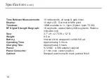
Page 15: ...ph 16 segments approximately 3dB segments Relative indication only Size 3 7 x H x 2 75 W x 1 2 D Weight 8 5 oz Battery Internal shrink wrapped 4 cell AA NiCad Operating Time Approximately 5 Hours Charging Time Approximately 8 hours Power 9 12VDC AC90 adapter supplied Power Connector 2 1 mm coax center positive Cabinet Stamped aluminum with black painted finish Specifications cont ...

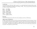
Page 16: ...FM broadcast notch filter will remove the influence from local FM stations SERIAL DATA INTERFACE In order to download the memories of the M1 the Optoelectronics Optolinx serial data interface is need ed The Optolinx universal PC interface adapts for use with a wide variety of receivers frequency coun ters and frequency recorders for the purpose of computer control of a receiver and downloading mem...

Page 17: ...onics reserves sole right to make this determination No other warranties are expressed or implied including but not limited to the implied warranties of merchantability and fitness for a particular purpose Optoelectronics Inc is not liable for consequen tial damages WARRANTY Products under warranty must be returned transportation prepaid to Optoelectronics service center All parts replaced and lab...

Page 18: ...insurance recommended Note Carriers will not pay for damage if items are improperly packaged 5 Proper remittance including return shipping if applicable Visa MasterCard number with expiration date Money order Company PO etc Note Personal checks are held for a minimum of two weeks before shipment Address all items to Optoelectronics Inc Service Department 160 West Camino Real 233 Boca Raton FL 3343...

Reviews: