


114
Please go to
X417H417 H417 H
Figure 6-2
X
to modify zoom, focus, and iris. Go back to
X418H418H 418H
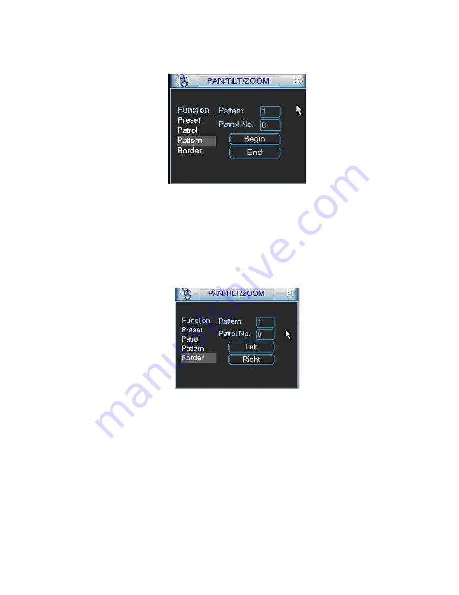
Figure 6-9
X
and click end
button.
You can memorize all these setups as pattern 1.
6.2.6 Activate Pattern Function
Figure 6-9
In
X 4 1 9 H 4 1 9 H 419 H
Figure 6-6
X
input mode value in the No. blank, and click pattern button.
6.2.7 Border Setup
In
X 4 2 0 H 4 2 0 H 420 H
Figure 6-5
X
, click border button. The interface is shown as in
X421H421H 421H
Figure 6-10
X
.
Please go to
X422H422 H422 H
Figure 6-2
X
, use direction arrows to select camera left limit, and then please go to
X 4 2 3 H 4 2 3 H 4 2 3H
Figure 6-10
X
and click left limit button
Repeat the above procedures to set right limit.
6.2.8 Activate Border Function
Figure 6-10
In
X 4 2 4 H 4 2 4 H 424 H
Figure 6-6
X
, click auto scan button, the system begins auto scan. Correspondingly, the auto
scan button changes to stop button.
Click stop button to terminate scan operation.
6.2.9
Flip
In
X 4 2 5 H 4 2 5 H 425 H
Figure 6-6
X
, click page switch button, you can see an interface is shown as below. See
X 4 2 6 H 4 2 6 H 4 2 6H
Figure 6-11
X
. Here you can set auxiliary function.
Click page switch button again, system goes back to
X 4 2 7 H 4 2 7 H 427 H
Figure 6-2
X
.


