23
Figure 3-4
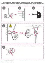
Figure 3-5
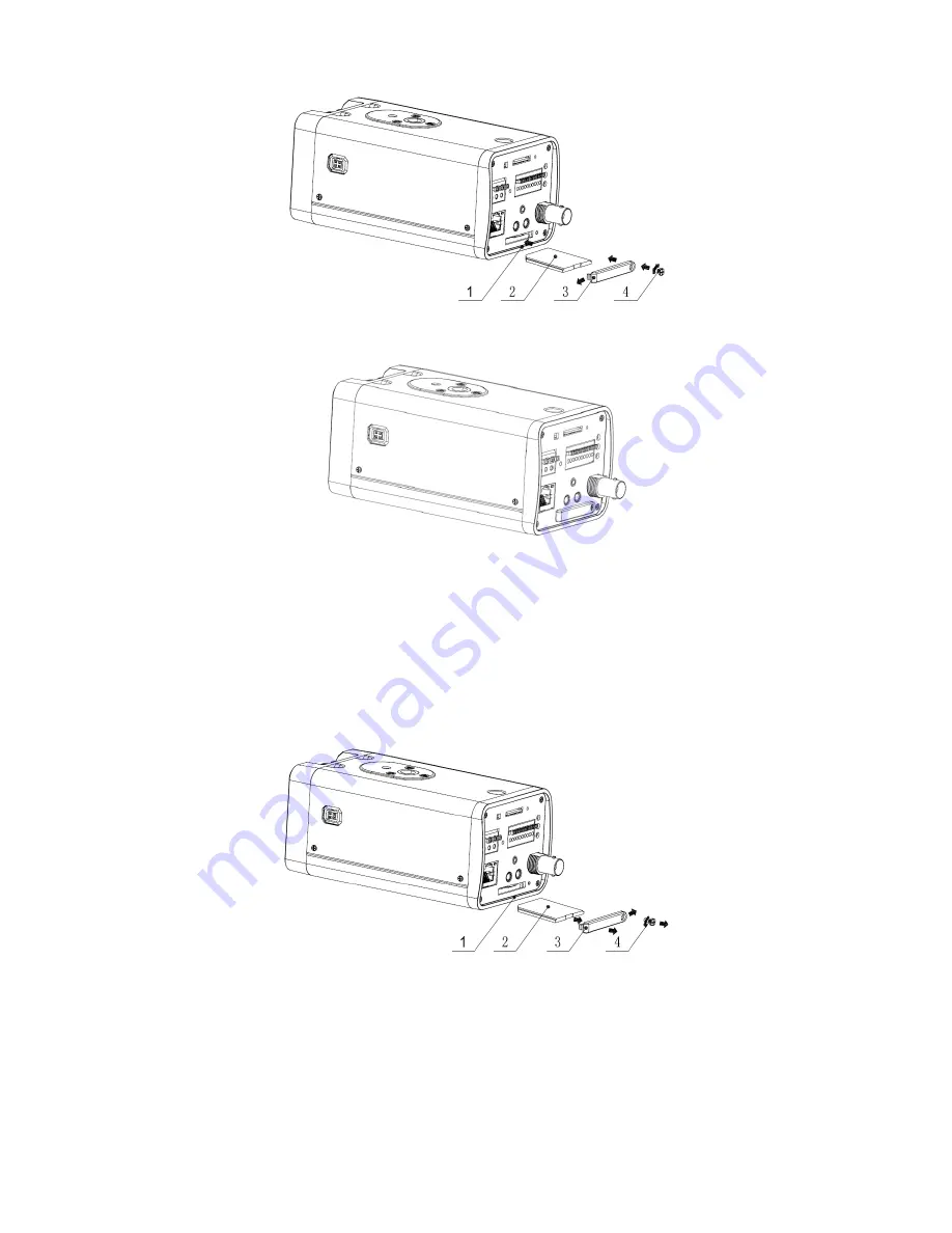
3.2.2 Remove
Please follow the steps listed below to remove SD card. The interface is shown as Figure 3-6.
Use the screwdriver to loosen the screw of SD card protection cap in the rear panel.
Remove the cap from the camera.
Follow the SD card direction to remove the SD card.
Insert the SD card protection cap.
Use the screwdriver to fix the screw to secure the protection cap.
Figure 3-6
3.3
3G Card
3.3.1 Installation
The 3G card installation is the same with the SD card.
Please follow the steps listed below to install 3G card. The interfaces are shown as Figure 3-7
and Figure 3-8.