OPTIMUM
M A S C H I N E N - G E R M A N Y
Ersatzteile - Spare parts
Version 1.0 2017-03-13
55
Originalbetriebsanleitung
RD5
DE
6
6.1
Bohrkopf - Drilling head
Page 1: ...GB OPTIMUM M A S C H I N E N G E R M A N Y Operating Manual Version 1 0 Radial drilling machine Item no 3049050...
Page 2: ...in switch 17 1 13 Clamping Table 17 1 14 Personal protective equipment 17 1 15 Safety during operation 18 1 16 Safety during maintenance 18 1 16 1 Disconnecting and securing the radial drilling machin...
Page 3: ...ation 43 5 1 2 Restarting 43 5 2 Inspection and maintenance 44 5 3 Overview of lubrication points 44 5 4 Recommended wear and tear parts 49 5 5 Adjustment of clearance on cantilever and drilling head...
Page 4: ...inal operating instructions RD5 GB 8 5 4 Disposal of electrical and electronic components 79 8 5 5 Disposal of lubricants and coolants 80 8 6 Disposal via municipal collection facilities 80 8 7 RoHS 2...
Page 5: ...agraph Maintenance all maintenance works and functional tests are described which the operator must perform in regular intervals The illustration and information included in the present manual can pos...
Page 6: ...for accident prevention the prohibition warning and mandatory signs as well as the warning labels on the radial drilling machine If you would like to order another operating manual for your machine pl...
Page 7: ...ch specific danger and its possible consequences 1 2 2 Other pictograms Symbol Alarm expres sion Definition consequence DANGER Impending danger that will cause serious injury or death to people WARNIN...
Page 8: ...up Warning tilting danger Warning suspended loads Caution danger of explo sive substances Switching on forbidden Only switch when stopped Read the operating instruc tions before commission ing Pull o...
Page 9: ...hich is not in accord ance with the intended use We expressly point out that the guarantee or CE conformity will expire due to any constructive technical or procedural changes which had not been perfo...
Page 10: ...hen drilling make sure that the suitable speed is set depending on the diameter of the drill the pressure must only be such that the drill can cut without load if there is too much pressure the drill...
Page 11: ...plug of the machine and secure the main switch using a lock This will prevent it from being used by unauthorized persons The qualifications of the personnel for the different tasks are mentioned below...
Page 12: ...an operational risk analysis in accordance with 6 of the Work Safety Act The operator must Obligations of the operator have obtained a training regarding the handling of the radial drilling machine k...
Page 13: ...yourself and other personnel working with the radial drilling machine The possible consequences are injuries may occur due to workpiece or parts of workpieces flying off contact with rotating parts fa...
Page 14: ...h button the radial drilling machine must be switched off Shifting rod with trip device on the drilling spindle After touching the shift rod the drilling machine must be switched off The drilling mach...
Page 15: ...afety Version 1 0 2017 03 13 Page 15 Original operating instructions RD5 GB 1 10 1 Prohibition warning and mandatory signs INFORMATION All warning signs must be legible They must be checked regularly...
Page 16: ...pindle keeps turning for a short time even after actuating the EMERGENCY STOP push button depending on the preset speed Img 1 1 EMERGENCY STOP 1 12 Extendable shift rod CAUTION The drilling spindle ke...
Page 17: ...pieces flying off at high speed Securely fix the workpiece on the machine foot or on the drilling table 1 14 Personal protective equipment For some works you need personnel protective equipment as pro...
Page 18: ...ng work suit and if necessary a hairnet Do not use protective gloves when drilling 1 16 Safety during maintenance Inform the operators in good time of any maintenance and repair works Report all safet...
Page 19: ...n The operator of the machine must ensure that the electrical systems and operating equipment are inspected with regards to their proper condition namely by a qualified electrician or under the superv...
Page 20: ...capacity in steel S235JR mm 42 Drilling capacity in cast steel mm 55 Tapping in steel S235JR M24 Tapping in cast steel M38 Feed speed spindle sleeve mm rotation 3 stages 0 05 0 09 0 153 Automatic dri...
Page 21: ...ise emission also depends on production engineering factors e g speed material and clamping conditions INFORMATION The specified numerical value represents the emission level and does not necessarily...
Page 22: ...ble exposure level might be different from country to country due to national regulations This information about the noise emission should however allow the operator of the machine to more easily eval...
Page 23: ...iginal operating instructions RD5 GB 2 3 Space required for the machine 2 3 1 Work area Keep a work area of at least one metre around the machine free for operation and mainte nance Distance from the...
Page 24: ...essories Toolbox contains 1 x oil bottle for oiler 1 x grease press for grease nipple 1 set of Allen keys 2 x drill drift wedge 1 x cross head and slotted screwdriver Including 1 x clamping table 6 x...
Page 25: ...e lifting and load suspension gear has sufficient load capacity and that it is in perfect condition Observe the accident prevention regulations issued by your Employers Liability Insurance Association...
Page 26: ...substructure The substructure must bear the load Transport the radial drilling machine to the installation site using a forklift truck Img 3 1 Distance from centre of gravity Disassemble the lateral...
Page 27: ...e on the pallet Take care with the centre of gravity of the radial drilling machine Lift the radial drilling machine with a crane carefully from the pallet Img 3 2 Load suspension for lifting WARNING...
Page 28: ...vibrations also at a distance of presses planing machines etc The substructure must be suitable for the radial drilling machine Also make sure that the floor has sufficient load bearing capacity and i...
Page 29: ...ty Please observe that there is tensile loading and additional punctual load on the foundation while turning the cantilever against the direction of the machine foot Check the horizontal orientation o...
Page 30: ...ase the smaller the cantilever can turn by itself around the col umn when the clamping lever is released Use the adjusting shims in the scope of supply at positions to Align the machine with the adjus...
Page 31: ...ine bed 3 7 Top up oil check oil level ATTENTION The radial drilling machine is delivered without oil filling First fill in oil before starting the radial drilling machine Oil sight glass spindle gear...
Page 32: ...hardens when the solvent evaporates As soon as the lacquer is applied the solvent evaporates into the air The binder becomes felted and a dry film is formed This process is reversible i e the binder...
Page 33: ...an Maintenance on page 43 Check if all spindles are running smoothly 3 10 1 Electrical connection CAUTION Install the connection cable of the machine in such a way that people will not stumble over it...
Page 34: ...devices and tighten up the screws if necessary WARNING The use of improper tool holders or their operation at inadmissible speeds constitutes a hazard Only use the tool holders e g drill chuck which...
Page 35: ...Item Designation Item Designation 1 Clamping lever 2 Selection of spindle sleeve feed 3 Move hand wheel on drilling head 4 Quill lever 6 Direction of rotation lever 5 Gear lever 7 Extendable shift ro...
Page 36: ...and the material Use the tables on the machine INFORMATION The data of the speed tables are guide values In some cases it may be advantageous to increase or decrease these values A cooling or lubrica...
Page 37: ...oads on the operator or assembler may be exceeded Turn the cantilever towards the rear and load the table with a crane or another suitable loading device Recommended threshold values when lifting and...
Page 38: ...ength of shift rod When shift rod comes into contact with something or when the workpiece or the clamp breaks loose the machine must shut down Img 4 1 Shift rod extended 4 5 Moving drilling head Img 4...
Page 39: ...le sleeve down with the feed lever Img 4 3 Clamping lever of cantilever INFORMATION Move the spindle sleeve down with the feed lever The spindle starts to turn as soon as it leaves the upper end posit...
Page 40: ...p condition Set the rotational direction control lever to the neutral position Unlock the emergency stop switch again 4 10 Power failure Restoring readiness for operation Put the rotation direction sh...
Page 41: ...ll spin dle Check and if necessary clean the conical seat in the drilling spindle and at the taper man drel of the tool or the drill chuck Press the taper mandrel into the drilling spindle 4 12 2 Unfi...
Page 42: ...by the rotation movement high temperatures are generated on the cutting edge of the tool Cool down the tool while drilling In this way you attain better working results and a longer dura bility of th...
Page 43: ...them in accordance with current legal requirements on the environment Collect leakages Do not re introduce liquids spilt outside the system during repair or as a result of leakage from the reserve ta...
Page 44: ...2 Inspection and maintenance The type and level of wear depends to a large extent on the individual usage and operating conditions Any indicated intervals therefore are only valid for the correspondin...
Page 45: ...h Mobil Greaserex 47 with one stroke of the grease press every day Oiling Top front of gearbox Oil once a day until it is com pletely filled with Mobilgear 626 oil every day Oiling Oil right side of g...
Page 46: ...earbox once a week until it is com pletely filled with Mobilgear 626 oil Weekly Bare steel parts Lubricating Rub bare steel parts with an acid free lubricating oil e g Mobilgear 626 or engine oil Cool...
Page 47: ...ns RD5 GB Every month Oil sight glass spindle gear Visual inspection Check oil level Oil sight glass gear Lifting device Cantilever Visual inspection Check oil level Spindle Lifting device Cantilever...
Page 48: ...of the cantilever at least annually Cooling lubricant system Replacing Cleaning Disinfect Cooling lubricants and tanks on page 52 Inspection plan for water mixed cooling lubricants on page 53 after 3...
Page 49: ...el using the entire travel on the cantilever Adjustment of horizontal roll guidance Undo screws 3 after 4 at the latest 5 years Positions switch Spindle contracted extended Replace the posi tion switc...
Page 50: ...ead on cantilever 5 6 Adjustment of position switch on clamping lever The clamping lever must be pulled firmly so that the spindle drive switches on If the spindle no longer turns or the spindle rotat...
Page 51: ...pany St rmer Maschinen GmbH Dr Robert Pfleger Str 26 D 96103 Hallstadt can provide a customer service technician however the request for a customer serv ice technician can only be made via your specia...
Page 52: ...than 10 6 ml there is an increase in nitrite content to more than 20 ppm mg 1 or nitrate content to more than 50 ppm mg 1 there is an increase in the N nitrosodiethanolamine NDELA to more than 5 ppm...
Page 53: ...s 0 5 based on initial filing Measures in accordance manufacturer s rec ommendations 1 0 based on initial filing Replace cooling lubricant clean cooling lubri cant circulation system Usage concentrati...
Page 54: ...OPTIMUM M A S C H I N E N G E R M A N Y Version 1 0 dated 2017 03 13 Page 54 Original operating instructions Coolant lubricating EN coolant_GB fm...
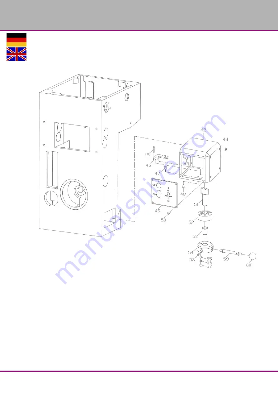
Page 55: ...OPTIMUM M A S C H I N E N G E R M A N Y Ersatzteile Spare parts Version 1 0 2017 03 13 55 Originalbetriebsanleitung RD5 DE 6 Ersatzteile Spare parts 6 1 Bohrkopf Drilling head...
Page 56: ...OPTIMUM M A S C H I N E N G E R M A N Y Ersatzteile Spare parts Version 1 0 2017 03 13 56 Originalbetriebsanleitung RD5 DE 6 2 Getriebe Bohrkopf R ckseite Gear of drilling head rear...
Page 57: ...t 4 030490500120 21 Klemmhebel Clamping Lever 1 030490500121 22 Kugel Ball 1 1 2 030490500122 23 Exzentrische Welle Eccentric Shaft 1 030490500123 23 1 Schraube Bolt 1 M4x60 24 Welle Shaft 1 030490500...
Page 58: ...0490500152 53 Lager dauergeschmiert Self Lubricating Bearing 1 LFB2025 030490500153 54 Flansch Flange 1 030490500154 55 Stahlkugel Ball Steel 1 5 16 030490500155 56 Feder Wire Spring 1 030490500156 57...
Page 59: ...OPTIMUM M A S C H I N E N G E R M A N Y Ersatzteile Spare parts Version 1 0 2017 03 13 59 Originalbetriebsanleitung RD5 DE 6 3 Getriebe Bohrkopf Gear of drilling head...
Page 60: ...l 2 5 16 030490500220 21 Welle Shaft 1 030490500221 22 Dichtung Oil Seal 1 30x45x8 030490500222 23 Schalthebel Switch lever 1 030490500223 24 Gabel Fork 1 030490500224 25 Platte Plate 1 030490500225 2...
Page 61: ...Passfeder Key 1 7x12 030490500279 80 Zahnrad Gear 1 030490500280 81 Sicherungsring Retainer 1 22 030490500281 82 Lager Bearing 1 6004ZZ 0406004ZZ 83 Sicherungsring Retainer 1 35 030490500283 84 Zahnr...
Page 62: ...ey 1 0304905002110 111 Kugel Ball 2 3 8 0304905002111 112 Vorschubgriff Feed Handle 2 0304905002112 113 Federstift Spring Pin 2 5x50 0304905002113 114 Mutter Nut 1 0304905002114 115 Kupplungsgeh use C...
Page 63: ...OPTIMUM M A S C H I N E N G E R M A N Y Ersatzteile Spare parts Version 1 0 2017 03 13 63 Originalbetriebsanleitung RD5 DE 6 4 S ule Column...
Page 64: ...bdeckung oben Bearing cover of the top 1 030490500319 20 Federring Spring Washer 1 1 2 030490500320 21 Schraube Bolt 1 030490500321 22 Arm Arm 1 030490500322 23 Schraube Bolt 2 M6x25 24 Schraube Bolt...
Page 65: ...aring 1 51105 04051105 57 Exzentrische Welle Eccentric Shaft 1 030490500357 58 Bolzen Bolt 1 M6x40 59 Klemmring Ring Clamp 1 030490500359 60 Bolzen Bolt 1 M10x25 61 Klemmhebel Locking lever 1 03049050...
Page 66: ...905004181 19 Geh use Worm hosing 1 030490500419 20 Schraube Bolt 4 M8x40 21 Oilschauglas Gage Fuel Level 1 030490500421 22 Verschluss Plug 2 P1 4 030490500422 23 Kugellager Bearing 1 30303 04030303 24...
Page 67: ...OPTIMUM M A S C H I N E N G E R M A N Y Ersatzteile Spare parts Version 1 0 2017 03 13 67 Originalbetriebsanleitung RD5 DE 6 6 K hlmitteleinrichtung Coolant device...
Page 68: ...eibe Washer 4 M6 3 Screw Schraube 4 M6x16 4 Kniest ck Elbow 1 030490500504 5 Kunstoffleitung Net Plastic Pipe 1 030490500505 6 Anschluss Male Connector 1 030490500506 7 Kniest ck Elbow 1 030490500507...
Page 69: ...A N Y Ersatzteile Spare parts Version 1 0 2017 03 13 69 Originalbetriebsanleitung RD5 DE 6 7 Schaltplan Wiring diagram K hlmittelpumpe Coolant pump H henverstellung Ausleger Cantilever height adjustm...
Page 70: ...Emergency stop Drehrichtung Gegenuhrz Counter clockwise rotation Drehrichtung Gegenuhrzeigersi Drehrichtung Gegenuhrzeigersi Ausleger ab Cantilever down Drehrichtung Uhrzeigersinn Clockwise rotation...
Page 71: ...OPTIMUM M A S C H I N E N G E R M A N Y Ersatzteile Spare parts Version 1 0 2017 03 13 71 Originalbetriebsanleitung RD5 DE Maschinenlampe Machine lamp Zeitrelais Bremse Brake time relays Bremse Brake...
Page 72: ...elpumpe Motor coolant pump 0 1 KW 03049050M3 M4 Elektomagnet Spindelbremse Electromagnetic spindle brake 03049050M4 ML Maschinenleuchte Machine light ONN IMS 24v 03049050ML Q1 Hauptschalter Main switc...
Page 73: ...ropa 150 VG 100 CLP 100 Aral Degol BG 100 BP Energol GR XP 100 SPARTAN EP 100 Kl beroil GEM 1 100 Mobilgear 627 Shell Omala 100 Meropa 100 VG 68 CLP 68 Aral Degol BG 68 BP Energol GR XP 68 SPARTAN EP...
Page 74: ...Maccurat D68 ESSO Febis K68 LAMORA D 68 Mobil Vactra Oil No 2 Shell Tonna S2 M 68 Way lubricant X 68 le f r Hochfre quenzspindeln Oils for Built in spindles Huiles pour broches haute vitesse VG 68 De...
Page 75: ...ps do not come out of the drill hole Drill blunt No or too little cooling Select another speed Extract drill more often during work Sharpen or use new drill Use cooling agent Drill tip is running off...
Page 76: ...the intended environmental conditions Follow the instructions and information on the transport box Term Explanation Drill drift Tool to release the bit or the drill chuck from the drill spindle Drill...
Page 77: ...ored for more than three months or are stored under different environmental conditions than those spec ified here Environmental conditions storage and transport on page 21 Prescribed position of the p...
Page 78: ...ual is disregarded Inattentive or incorrect handling and use of improper equipment Unauthorised modifications and repairs Insufficient installation and safeguarding of the machine Disregarding the ins...
Page 79: ...Disposal of the old device INFORMATION Please take care in your interest and in the interest of the environment that all component parts of the machine are only disposed of in the intended and admitt...
Page 80: ...ates that the product must not be handled as common household waste but that is needs to be disposed of at a central collection point for recycling Your contribution to the correct disposal of this pr...
Page 81: ...EMC Directive 2014 30 EC Low Voltage Directive 2014 35 EC The safety objective meet the requirement of EC Directive 2006 42 EC The following harmonized standards were applied EN 1837 1999 A1 2009 Safe...
Page 82: ...eset 40 F Fixing 30 I Inspection 44 Installation 28 Intended use 9 L Load suspension point 25 M Machine switch off 40 switch on 39 Maintenance 43 44 Malfunctions 75 Misuse 9 O Obligations of the opera...