


Step 4
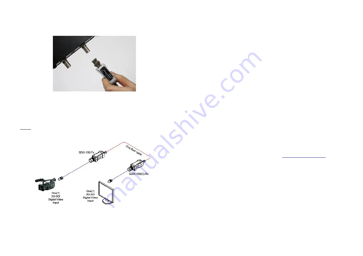
Connect the Rx side of SDIX-100(C) to the SDI receptacle of a Display
directly. Do
NOT
recommend to use any intermediate cable or adapter
between them. It may deteriorate the signal transmission performance.
Figure 4
– Rx module of SDIX-100(C)
Step 5
Power ON the SDI source and Display.
Note:
Both of Tx and Rx modules of SDIX-100(C)
must be connected by
+5V power adaptors.
Figure 5
– Whole Connection of SDIX-100(C)
Step 7
If the system does not work properly, go to page 1-5, trouble shooting.
1-4 Installation (continued)
Troubleshooting
The display shows only black screen.
Ensure that all AC and DC plugs and jacks used by external power supplies
are firmly connected.
Ensure that the SDI connector is firmly plugged in to the SDI source and SDI
display. Ensure that the Tx and Rx module parts plug correctly to the SDI
source and SDI display, respectively.
Check if the SDI source and SDI display are powered on and properly booted.
Reset the system by de-plugging and re-plugging the Tx SDI module or Rx
SDI module. Re-boot up the system while connecting the SDIX-100(C).
Screen is distorted or displays noises.
Ensure the quality of SDI source and check the extension length of fiber.
SDIX-100 guarantees the length up to 30Km@3G
Maintenance
No special maintenance is required for the SDIX-100 and power supplies.
Ensure that the cables and power modules are stored or used in a benign
environment free from liquid or dirt contamination.
There are no user serviceable parts. Refer all service and repair issues to
Opticis.
Technical Support and Service
For commercial or general product support, contact your reseller. For
technical service, contact Opticis by email
website at www.opticis.com.
1-5 Troubleshooting, Maintenance, Technical Support


