


OPTICAL SYSTEMS DESIGN
DOC ID: 10111504
OSD2700F OPERATOR MANUAL
PAGE 16
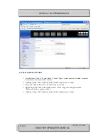
3.3
OSD2700F OPERATION
When using the OSD2700F for the first time, check that the unit is in good condition with no visible
damage.
Connect the unit to an appropriate power source and check that the indicators illuminate accordingly on
power up (see Table 4) after all other connections have been made.
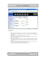
3.3.1
CABLE CONNECTIONS
It is necessary to follow the cable specifications below when connecting the switch to your network.
Use appropriate cables that meet your speed and cabling requirements.
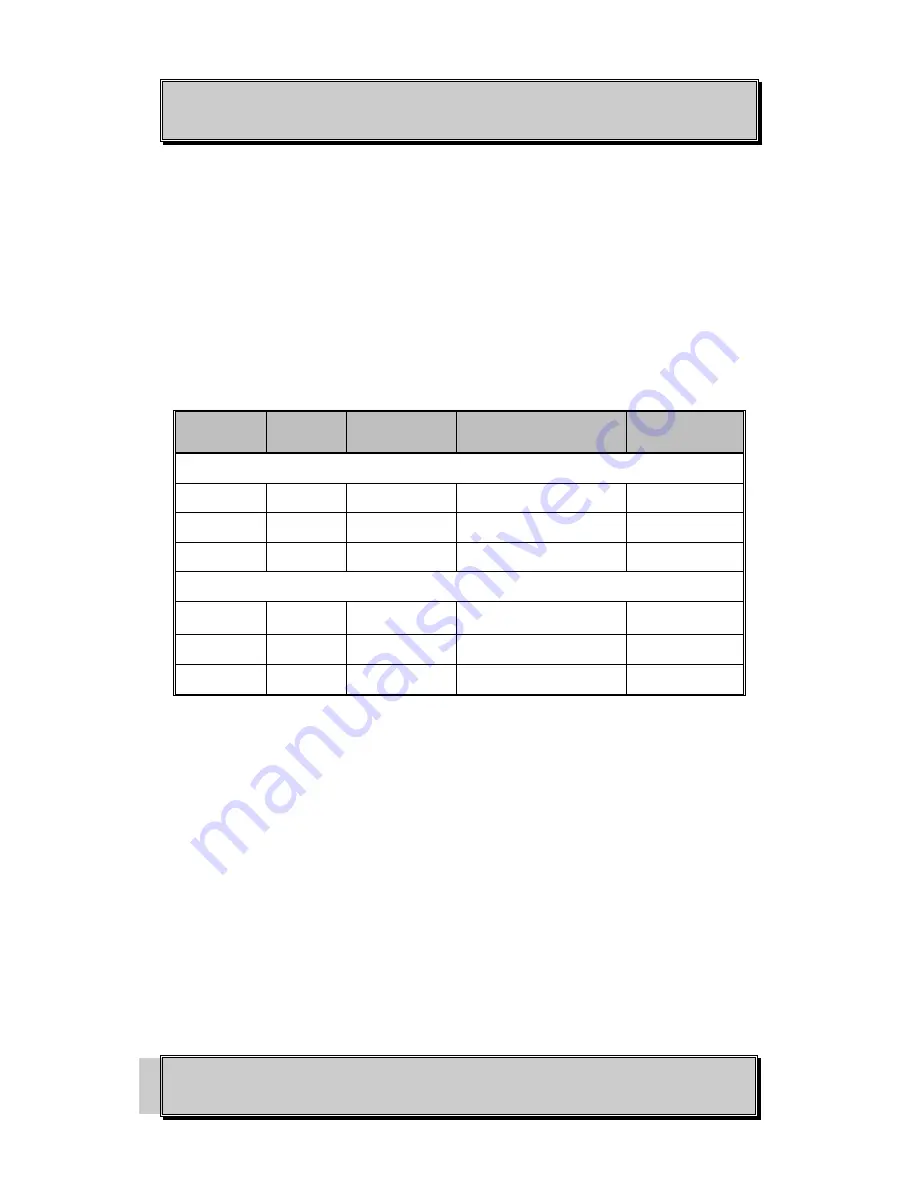
TABLE 5: CABLE SPECIFICATIONS
Speed
Connector
Port Speed
Half/Full Duplex
Cable
Max.
Distance
Copper RJ45
10Base-T
RJ-45
10/20 Mbps
2-pair UTP/STP Cat. 3, 4, 5 100m
100Base-TX
RJ-45
100/200 Mbps
2-pair UTP/STP Cat. 5
100m
1000Base-T
RJ-45
2000 Mbps
4-pair UTP/STP Cat. 5
100m
SFP
1000Base-SX Duplex LC
2000 Mbps
MMF (62.5
µ
m)
550m
2km
1000Base-LX Duplex LC
2000 Mbps
SMF (9
µ
m)
10, 40, 60km
1000Base-BX Duplex LC
2000 Mbps
SMF (9
µ
m)
70km
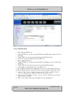
Step 1: First, ensure the power of the switch and end devices are turned off.
Step 2: Prepare cable with corresponding connectors for each type of port in use.
Step 3: Consult Cable Specifications Table on previous page for cabling requirements based on
connectors and speed.
Step 4: Connect one end of the cable to the switch and the other end to a desired device.
Step 5: Once the connections between two end devices are made successfully, turn on the power and
the switch is operational.