background image


81 


[View] 

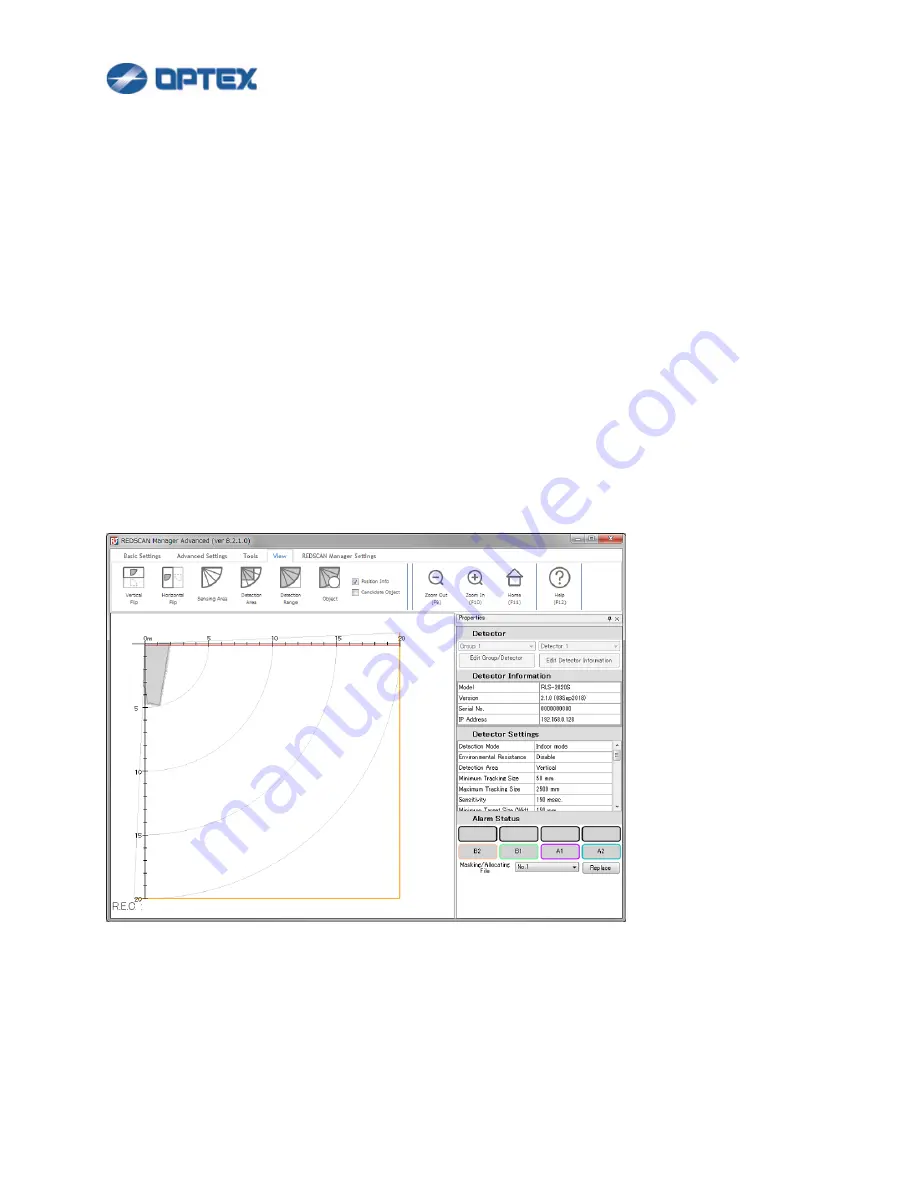
The graphics of REDSCAN Manager can be customized. 


Click View menu. Select preferable settings. 


Vertical Flip: Flips the map vertically. 


Horizontal Flip: Flips the map horizontally. 


Sensing Area: Shows the all sensing area. Except in the detection area, objects in sensing area are 

recognized but not detected, and no alarm is issued. 


Detection Area: Shows the detection area. Objects in the detection area are detected and alarm is 

issued. 


Detection Range: Shows the vertical and horizontal limits of the detection area. 


Object: Detected object is drawn as a circle or filled circle. 


Position Info: Displays position and size information of detected/candidate objects. 


Candidate Object: Displays candidate objects as blue circles. If candidate object goes beyond 

thresholds, it becomes red circle and alarm is issued. 


Summary of Contents for RLS-2020I

Page 1: ...vanced is Windows application software to configure REDSCAN series RLS 2020I RLS 2020S RLS 3060L and RLS 3060SH Once RLS 3060SH L were adjusted with REDSCAN Manager Ver 8 or later do not readjusted with its earlier than Ver 8 in order to avoid unexpected activations ...

Page 2: ...t displayed on REDSCAN Manager 22 REDWALL Event Code does not work on VMS 22 REDWALL Event Code does not work on Milestone XProtect 23 Many False Alarms 23 Malfunction 23 REDSCAN Manager Function List 24 Install of REDSCAN Manager 24 PC Settings for REDSCAN Manager 25 Login 27 Group Registration 28 Connecting to REDSCAN 31 Area Set 34 Detection Mode Basic Settings RLS 2020 series 38 Detection Mode...

Page 3: ...2020 series RLS 3060SH or RLS 3060L version 8 0 0 or later 66 REDWALL Event Code Settings 68 Terminal Settings 70 Network Settings 74 Detector Authentication 75 Export Import 76 Snapshot 78 Recording 79 Playback 80 View 81 REDSCAN Manager Settings 82 Disconnecting REDSCAN 84 REDSCAN Manager Glossary 85 ...

Page 4: ... minimum sequence to set up REDSCAN series Install of REDSCAN Manager 1 Download the latest version of REDSCAN Manager Advanced installer from the web page http www optex co jp e redwall download index html 2 Start the installer 3 Follow the instructions ...

Page 5: ... TCP IP under General and set the IP address and subnet mask from Properties Windows 8 1 1 On the taskbar click Start click Search enter ncpa cpl and press Enter key 2 Select Local Area Connection to which the REDSCAN unit is connected and then display Properties 3 Select Internet Protocol Version 4 TCP IPv4 under General and set the IP address and subnet mask from Properties Windows 10 1 Enter nc...

Page 6: ...m the list 4 Double click on REDSCAN Manager Advanced to open Properties 5 On the General tab select Allow Connect and click OK On the Advanced settings tab check all profiles If there are multiple REDSCAN Manager Advanced in the list change settings of the all REDSCAN Manager Advanced Windows 10 1 Enter Firewall cpl in Search on the taskbar press Enter key 2 On the left of the screen click Advanc...

Page 7: ...t authentication information and click OK Default Password laser306 Or if you changed the password please enter it in Password window to access the unit RLS 2020 series User ID and Password can be changed Default User ID REDSCAN Default Password OPTEX Once the connection between REDSCAN Manager Advanced software and the REDSCAN unit was established the authentication information was stored But if ...

Page 8: ...ll 3 boxes and allow the access 3 If REDSCAN Manager is started for the first time Initial Settings are required 1 Enter preferable name of target REDSCAN 2 Select model name of the target 3 Enter IP address of the target Default IP address of main port of REDSCAN mini is 192 168 0 126 4 lick Next 5 If the settings are ok click Complete ...

Page 9: ...9 4 Click Connect button at upper left If Windows Firewall Message appears check all 3 boxes and allow the access Click connect button again ...

Page 10: ...easing false alarm RLS 2020 1 If Area Set is not done yet the 2nd button is active Click the Area Set button 2 Dialog box will appear Click OK Area Set will be completed in 15 seconds 3 Once Area Set is done the 2nd button is disabled To do Area Set again select Advanced Settings and click the 6th button ...

Page 11: ...ted in 20 seconds In caase of P2 Auto Tracing walking along the boundary of the area within 300 seconds When movement of the target object along the area boundary has finished before this time you can terminate the tracing without waiting for 300 seconds by clicking Finish 4 Once Area Set is done the 2nd button is disabled To do Area Set again select Advanced Settings and click the 6th button ...

Page 12: ...ic Settings RLS 2020 series Detection Mode Advanced Settings RLS 2020 series Detection Mode Basic Settings RLS 3060SH Detection Mode Advanced Settings RLS 3060SH Detection Mode Basic Settings RLS 3060L Detection Mode Advanced Settings RLS 3060L Area Masking RLS 2020 series RLS 3060SH or RLS 3060L version 8 0 0 or later Area Allocating RLS 2020 series RLS 3060SH or RLS 3060L version 8 0 0 or later ...

Page 13: ...specifications for details of the code If you do not use R E C skip this page 1 Click I O Settings button the 4th button 2 Dialog box will appear Note Terminal tab of RLS 3060 can used for Version 8 0 0 or later Select preferable settings Default settings are Protocol UDP Detector ID The last byte of IP address of the REDSCAN Example 126 of 192 168 0 126 UDP Broadcast Destination Port Number 1234 ...

Page 14: ... multiple REDSCANs to Milestone XProtect set unique Port Number to each REDSCAN Over 12346 is recommended Transmission interval of Trouble code It specifies interval when trouble code is sent periodically Clear Code Timing It specifies the timing of clear code after the alarm is cleared Heartbeat for Device Monitoring If it is checked DM code is stored in R E C and sent by Transmission Interval of...

Page 15: ...s Select relay output settings If you do not use relay output skip this page 1 Click I O Settings button the 4th button 2 Dialog box will appear Click Terminal tab RLS 2020 Terminal tab screen Versions earlier than 2 1 0 ...

Page 16: ...pened Assign A1 DM to Output 1 3 Default settings are Signal Output 1 N C A1 A2 B1 B2 Signal Output 2 N C AM AR SO TR Signal Output 3 N C TA Not Select DM DM can be selected with V 2 0 3 or higher Signal Input RLS 2020S Only If Signal Input is closed the Action and the Response are done after the Judgement Time Signal input shorter than Judgement Time is ignored ...

Page 17: ...ent Masking Allocating Files is switched to next File Area Set Area Set is started Response is available when Switching to Next Masking Allocating File or Area Set is selected Select preferable Response which can be used to confirm that the action is triggered RLS 3060 Terminal tab screen Version 8 0 0 or later A1 A2 B1 B2 Output Select N O Normally Open or N C Normally Closed ...

Page 18: ...ng function A2 A2 area set by Allocating function B1 B1 area set by Allocating function B2 B2 area set by Allocating function AM Anti Masking AR Anti Rotation SO Soiling DQ Environmental Disqualification RLS 2020S Only TR Device Trouble TA Tamper Output DM Device Monitoring 3 Click Save button ...

Page 19: ...19 Disconnecting REDSCAN After settings and confirmation by walk test disconnect REDSCAN 1 Click Disconnect button the 5th button 2 Close REDSCAN Manager ...

Page 20: ...64 bit Microsoft Windows 10 Professional 32 bit Microsoft Windows 10 Professional 64 bit CPU Intel Core TM i5 CPU M 520 2 4GHz or above RAM 1 GB or above Graphics 1024 768 or above Network Ethernet 100BASE TX or above HDD free space 1 GB or above Microsoft and Windows are registered trademarks of Microsoft Corporation All other trademarks mentioned in this document are trademarks of their respecti...

Page 21: ...s used Refer below page for default settings of main and maintenance ports PC Settings for REDSCAN Manager Check network settings of the PC and REDSCAN Are they correct Try ping from the PC to REDSCAN Example Open command prompt and enter ping 192 168 0 126 Is Windows firewall opened for REDSCAN Manager PC Settings for REDSCAN Manager Check Windows firewall settings Control Panel Windows Firewall ...

Page 22: ...ics Performance setting in REDSCAN Manager Settings Interrupt Moderation of the NIC can prevents smooth graphics on the map Disable Interrupt Moderation of Adapter Settings on Windows REDWALL Event Code is not displayed on REDSCAN Manager Check R E C settings REDSCAN Manager requires broadcast or unicast UDP to show R E C REDWALL Event Code Settings If broadcast is selected the REDSCAN and the PC ...

Page 23: ...ng false alarm Adjust target size and sensitivity Detection Mode Basic Settings RLS 2020 series Detection Mode Basic Settings RLS 3060SH Detection Mode Basic Settings RLS 3060L Plants causing false alarm Adjust Ignoring Area from Ground check Adjust Detection Area and or adjust Masking Detection Mode Basic Settings RLS 2020 series Detection Mode Basic Settings RLS 3060SH Detection Mode Basic Setti...

Page 24: ...tall of REDSCAN Manager 1 Download the latest version of REDSCAN Manager Advanced installer from the web page http www optex co jp e redwall download index html 2 Start the installer 3 Follow the instructions Recommended PC Specifications ...

Page 25: ... TCP IP under General and set the IP address and subnet mask from Properties Windows 8 1 1 On the taskbar click Start click Search enter ncpa cpl and press Enter key 2 Select Local Area Connection to which the REDSCAN unit is connected and then display Properties 3 Select Internet Protocol Version 4 TCP IPv4 under General and set the IP address and subnet mask from Properties Windows 10 1 Enter nc...

Page 26: ...om the list 4 Double click on REDSCAN Manager Advanced to open Properties 5 On the General tab select Allow Connect and click OK On the Advanced settings tab check all profiles If there are multiple REDSCAN Manager Advanced in the list change settings of the all REDSCAN Manager Advanced Windows 10 1 Enter Firewall cpl in Search on the taskbar press Enter key 2 On the left of the screen click Advan...

Page 27: ...N and OPTEX To change Login password click Change Password button If you want to skip the Login from next time check the checkbox The PC remembers the password If you want to activate the Login again select REDSCAN Manager Settings menu and click Option button Select Enable in Login tab ...

Page 28: ...tector 1 To change registered information of Detector 1 click Edit Detector Information button Enter preferable name select target model and enter IP address of the target REDSCAN To show R E C on REDSCAN Manager enter R E C port number of the target REDSCAN REDSCAN Manager displays UDP R E C only 2 To register new unit click Edit Group Detector Information button ...

Page 29: ... of target unit To change the settings select the detector in the list and click Edit Detector button To delete a detector select the detector in the list and click Delete Detector button 3 To register new group click Edit Group Detector Information button Click Edit Group button ...

Page 30: ...ton Export 1 Select a group in the group list 2 Click Export button and save a xml file The selected group information is exported Import 1 Click Import button and select an exported xml file 2 If current group list does not have the name of the imported group the imported group is added to the list If current group list has the name of the imported group the group in the list is overwritten by th...

Page 31: ...t authentication information and click OK Default Password laser306 Or if you changed the password please enter it in Password window to access the unit RLS 2020 series User ID and Password can be changed Default User ID REDSCAN Default Password OPTEX Once the connection between REDSCAN Manager Advanced software and the REDSCAN unit was established the authentication information was stored But if ...

Page 32: ...1 Click Connect button at upper left If Windows Firewall Message appears check all 3 boxes and allow the access Click Connect button again Information of the REDSCAN will be displayed in Properties window ...

Page 33: ...Code R E C it will be displayed under the map When some object is detected in A1 A2 B1 B2 A1 A2 B1 B2 lamp shows it Masking Allocating file can be switched by selecting a file and click Replace button RLS 2020S or RLS 3060SH Drag Zoom bar to adjust map size Drag and drop the map to preferable position Home button enables to move the map to default position ...

Page 34: ...easing false alarm RLS 2020 1 If Area Set is not done yet the 2nd button is active Click the Area Set button 2 Dialog box will appear Click OK Area Set will be completed in 15 seconds 3 Once Area Set is done the 2nd button is disabled To do Area Set again select Advanced Settings and click the 6th button ...

Page 35: ...ted in 20 seconds In caase of P2 Auto Tracing walking along the boundary of the area within 300 seconds When movement of the target object along the area boundary has finished before this time you can terminate the tracing without waiting for 300 seconds by clicking Finish 4 Once Area Set is done the 2nd button is disabled To do Area Set again select Advanced Settings and click the 6th button ...

Page 36: ...ic Settings RLS 2020 series Detection Mode Advanced Settings RLS 2020 series Detection Mode Basic Settings RLS 3060SH Detection Mode Advanced Settings RLS 3060SH Detection Mode Basic Settings RLS 3060L Detection Mode Advanced Settings RLS 3060L Area Masking RLS 2020 series RLS 3060SH or RLS 3060L version 8 0 0 or later Area Allocating RLS 2020 series RLS 3060SH or RLS 3060L version 8 0 0 or later ...

Page 37: ...37 ...

Page 38: ...8 Detection Mode Basic Settings RLS 2020 series 1 Click Settings button the 3rd button 2 Dialog box will appear 3 Select preferable settings To set default settings click Restore default settings button ...

Page 39: ... be detected but false alarm can increase in harsh environment This mode shall be used for only indoor application Outdoor Mode RLS 2020S Only This option can be selected for general outdoor applications In this mode the special algorithm works to reduce false alarms caused by weather conditions e g rain snow or fog In order to reduce false alarms under harsh environment the Environmental Resistan...

Page 40: ...Click Show Advanced Settings Select preferable settings Detection Area Vertical Creating a detection area perpendicular to the ground such as wall protection Horizontal Creating a detection area in parallel with the ground such as ceiling protection Auto The direction is detected automatically when Area set is done ...

Page 41: ... Size the object is ignored After an object is detected the object is tracked while the size is smaller than Maximum Tracking Size Non Detection Zone Ignoring Area from Ceiling Vertical mode Only Objects near to ceiling are ignored In vertical detection area protruding objects on the ceiling can cause false alarm Enter the height of the ignoring area Auto Area Adjustment REDSCAN continues to learn...

Page 42: ...a for the detection Sensitivity Select sensitivity for the detection Anti Rotation This is to detect that someone rotated the detector The result is reflected to relay output and R E C Judgement Time Set the minimum duration for the detection Sensitivity Select sensitivity for the detection Soiling of Laser Window This is to detect dirt on Laser Window The result is reflected to relay output and R...

Page 43: ...ile fog rain or snow is detected DQ Output can be included in relay output and R E C Off Delay Time Set the time to deactivate the DQ Output after the detection of fog rain or snow is finished 3 Click Next button and click Save button in the next page to save the changes ...

Page 44: ...44 Detection Mode Basic Settings RLS 3060SH 1 Click Settings button the 3rd button 2 Dialog box will appear 3 Select preferable settings ...

Page 45: ...utput are disabled Indoor Ceiling Wall protection Mode Though Vertical mode is selected automatically by the mode this mode is available in horizontal installation for ceiling protection as well as vertical installation for wall protection In this mode slender target like human arm minimum 50 mm 2 in diameter can be detected Target size cannot be selected Environmental Resistance and DQ Output are...

Page 46: ...tays in the detection area H2 Horizontal Detection Area 2 This mode allows setting of a fan like detection area in the horizontal direction with a maximum radius of 30 m Approx 100 ft a spread angle of 190 degrees This mode detects intrusion into the detection area from any direction The Redscan will generate the alarm output 1 minute variable after the initial detection so long as the detected ob...

Page 47: ...arm is issued Minimum Target Size Width Default Middle The Size is to avoid false alarm caused by small object If an object is smaller than Minimum Target Size the object is ignored Detection Time Default 10 Can be changed when loitering detection is being selected Specify a time from intrusion of an object in a detection area to issuing an alarm 4 Click Next button and click Save button in the ne...

Page 48: ...ironments e g fog snow etc can work in Outdoor Fence Wall top protection and Outdoor Loitering detection Disable Select it for applications to control PTZ camera Response time of alarm is minimum but false alarm can increase in harsh environment such as a fog or snow Enable False alarm can be reduced by balanced detection ability Enhanced False alarm due to fog or snow is reduced but response time...

Page 49: ...tion Continuous After the RLS unit detects an object if the object remains in the detection area it keeps generating an alarm condition Preset After the RLS unit detects an object even though the object remains in the detection area the alarm will be restored after the preset time Default 60sec Adjustable range from 1 to 30000 sec Detection Width Adjustment H1 mode Only Setting for the width of H1...

Page 50: ...tection Anti Rotation This is to detect that someone rotated the detector The result is reflected to relay output and R E C Judgement Time Set the minimum duration for the detection Area Ratio Set the minimum area ratio for the detection Soiling of Laser Window This is to detect dirt on Laser Window The result is reflected to relay output and R E C Judgement Time Set the minimum duration for the d...

Page 51: ... rain or snow is detected DQ Output can be included in relay output and R E C Off Delay Time Set the time to deactivate the DQ Output after the detection of fog rain or snow is finished 3 Click Next button and click Save button in the next page to save the changes ...

Page 52: ...52 Detection Mode Basic Settings RLS 3060L 1 Click Settings button the 3rd button 2 Dialog box will appear 3 Select preferable settings ...

Page 53: ...option can be selected In this mode Environmental Resistance and DQ Output are disabled Indoor Fence Wall top protection mode Select this mode if you want to detect a person trying to climb over a fence in indoor environment Indoor Loitering detection mode version 8 0 0 or later Select this mode if you want to detect loitering object in indoor environment Detection Area Default H2 There are 2 opti...

Page 54: ...l detect an object that traverses the detection area Sensitivity Default Middle The Sensitivity is to avoid false alarm caused by instantaneous event If an object is detected longer than the Sensitivity time alarm is issued Minimum Target Size Width Default Middle The Size is to avoid false alarm caused by small object If an object is smaller than Minimum Target Size the object is ignored Detectio...

Page 55: ...ronments e g fog snow etc can work in Outdoor Fence Wall top protection and Outdoor Loitering detection Disable Select it for applications to control PTZ camera Response time of alarm is minimum but false alarm can increase in harsh environment such as a fog or snow Enable False alarm can be reduced by balanced detection ability Enhanced False alarm due to fog or snow is reduced but response time ...

Page 56: ...ation H1 H2 mode Only Setting for alarm duration after detection Continuous After the RLS unit detects an object if the object remains in the detection area it keeps generating an alarm condition Preset After the RLS unit detects an object even though the object remains in the detection area the alarm will be restored after the preset time Default 60sec Adjustable range from 1 to 30000 sec Non Det...

Page 57: ...n for the detection Area Ratio Set the minimum area ratio for the detection Soiling of Laser Window This is to detect dirt on Laser Window The result is reflected to relay output and R E C Judgement Time Set the minimum duration for the detection Area Ratio Set the minimum ratio of the dirty Laser Window for the detection DQ Output If it is enabled DQ Output is activated while fog rain or snow is ...

Page 58: ...58 Adjusting Detection Area 1 Click Setting button the 3rd button 2 Dialog box will appear Click Detection Area button ...

Page 59: ...on Area Pattern is predefined allocating area below Detection Area Pattern can be overridden by Area Allocating 3 Adjust size and position of the map as you like Click Zoom Out or Zoom In to adjust map size Drag and drop the map to preferable position Home button enables to move the map to default position ...

Page 60: ...r RLS 3060SH version 8 0 0 or later To set default settings click Restore default settings button 5 Adjust Offset Perimeter of detection area near background can be excluded by the Offset distance In vertical mode obstacles on the ground or floor can generate false alarm Also plants and small animals can cause false alarm To set default settings click Restore default settings button 6 Adjust detec...

Page 61: ...on enables to show current sensing situation By showing area update you can place and see dummy object as a mark and adjust the detection area based on the mark 2 Cut by Eraser tool Select one of Eraser tools and place the triangle cursor Click the place The triangle cuts detection area 3 Adjust by moving Blue Box Move mouse on a blue box The box becomes black Drag and drop the box ...

Page 62: ... click the box 7 Click Save button to save the change Detectable range based on a target size RLS 2020 Indoor Outdoor Indoor throw in mode Target size Black plate White plate 25 mm 1 in 50 mm 2 in 4 m 13 ft 5 m 16 ft 100 mm 4 in 8 m 26 ft 9 m 29 ft 150 mm 6 in 11 m 37 ft 13 m 41 ft 200 mm 8 in 15 m 49 ft 16 m 54 ft 300 mm 12 in 21 m 69 ft 23 m 77 ft ...

Page 63: ...23 ft 100 mm 4 in 10 m 32 ft 12 m 39 ft 150 mm 6 in 14 m 46 ft 17 m 56 ft 200 mm 8 in 18 m 59 ft 22 m 72 ft 300 mm 12 in 25 m 82 ft 32 m 105 ft 450 mm 18 in 33 m 108 ft 44 m 144 ft 550 mm 22 in 49 m 161 ft 600 mm 24 in 40 m 131 ft Reflectivity of Black plate 10 Reflectivity of White plate 90 Detectable range depends on the reflectivity of target and its shape Need to confirm the detectable range w...

Page 64: ...File Number tab RLS 2020S or RLS 3060SH The file contains masking allocating settings Applied file can be switched by Relay Input File Name can be changed 2 Select Enable 3 Select Area Masking 4 Select Set Area 5 Click preferable area on the map The black box means masking area Objects in the masking area are ignored To cancel the masking area select Delete Area and click the area To move the map ...

Page 65: ...e button Note Block size of Area Masking Allocating differs depending on model and setting RLS 2020 series 200 mm 0 66 ft RLS 3060 series 300 mm 0 98 ft RLS 3060SH version 8 0 0 or later with detection range expansion 500 mm 1 64 ft ...

Page 66: ...t File Name can be changed 3 To Allocate Area 1 Select File Number RLS 2020S or RLS 3060SH The file contains masking allocating settings Applied file can be switched by Relay Input 2 Select Enable 3 Select Area Allocating 4 Select Set Area Select A1 A2 B1 or B2 5 Click preferable area on the map The purple box means A1 area When objects are detected in the purple area A1 is reported by REDWALL Eve...

Page 67: ...e whole area becomes A1 4 Save the changes Click Save button Note Block size of Area Masking Allocating differs depending on model and setting RLS 2020 series 200 mm 0 66 ft RLS 3060 series 300 mm 0 98 ft RLS 3060SH version 8 0 0 or later with detection range expansion 500 mm 1 64 ft ...

Page 68: ...specifications for details of the code If you do not use R E C skip this page 1 Click I O Settings button the 4th button 2 Dialog box will appear Note Terminal tab of RLS 3060 can used for Version 8 0 0 or later Select preferable settings Default settings are Protocol UDP Detector ID The last byte of IP address of the REDSCAN Example 126 of 192 168 0 126 UDP Broadcast Destination Port Number 1234 ...

Page 69: ... multiple REDSCANs to Milestone XProtect set unique Port Number to each REDSCAN Over 12346 is recommended Transmission interval of Trouble code It specifies interval when trouble code is sent periodically Clear Code Timing It specifies the timing of clear code after the alarm is cleared Heartbeat for Device Monitoring If it is checked DM code is stored in R E C and sent by Transmission Interval of...

Page 70: ...s Select relay output settings If you do not use relay output skip this page 1 Click I O Settings button the 4th button 2 Dialog box will appear Click Terminal tab RLS 2020 Terminal tab screen Versions earlier than 2 1 0 ...

Page 71: ...pened Assign A1 DM to Output 1 3 Default settings are Signal Output 1 N C A1 A2 B1 B2 Signal Output 2 N C AM AR SO TR Signal Output 3 N C TA Not Select DM DM can be selected with V 2 0 3 or higher Signal Input RLS 2020S Only If Signal Input is closed the Action and the Response are done after the Judgement Time Signal input shorter than Judgement Time is ignored ...

Page 72: ...ent Masking Allocating Files is switched to next File Area Set Area Set is started Response is available when Switching to Next Masking Allocating File or Area Set is selected Select preferable Response which can be used to confirm that the action is triggered RLS 3060 Terminal tab screen Version 8 0 0 or later A1 A2 B1 B2 Output Select N O Normally Open or N C Normally Closed ...

Page 73: ...ng function A2 A2 area set by Allocating function B1 B1 area set by Allocating function B2 B2 area set by Allocating function AM Anti Masking AR Anti Rotation SO Soiling DQ Environmental Disqualification RLS 2020S Only TR Device Trouble TA Tamper Output DM Device Monitoring 3 Click Save button ...

Page 74: ...ings Caution IP addresses of Main Port and Maintenance Port must be in different network segment For example to set 192 168 1 to Main port change IP address of Maintenance Port to another network segment 3 Save the changes Click Save button The unit is restarted Note Change network settings of the PC for connecting to new IP address ...

Page 75: ...were changed by WEB browser or other REDSCAN Manager software entering user ID and password which were stored in the REDSCAN unit can be required If you forget the detector s authentication information you need to initialize the detector unit to restore the factory default Refer to the INSTALLATION INSTRUCTION RLS 3060L pg 7 RLS 3060SH RLS 2020I S pg 8 for how to return to the factory default sett...

Page 76: ...k Import Export button the 9th button 2 Dialog box will appear 3 Export To export settings Click Export Setting button Settings are exported to xml file 4 Import To import settings select Detection Settings Event Code and I O Settings and or Network Settings Click Import Setting button and select xml file The settings are imported to the detector ...

Page 77: ...77 Detection Settings contains settings in pages below I O Settings contains settings in pages below Network Settings contains settings in pages below ...

Page 78: ...apshot This function enables capturing current GUI image of REDSCAN Manager 1 Click Tools menu 2 Click Snapshot button Captured image is shown in dialog box 3 Save Click Save button and enter JPEG file name ...

Page 79: ... Select conditions to trigger recording Refer INSTALLTION INSTRUCTIONS or REDWALL Event Code specifications for details of the code Save Folder Select a folder in which recorded file is saved File Name Select base name of recorded file 3 Start and stop recording Click the immediate recording button recording of data starts immediately Click the record start button it enters the standby state and r...

Page 80: ... Click Playback button Folder Select folder of recorded files File List Recorded files in the folder are displayed Date Recorded day and time of select file are displayed R E C R E C of selected file is displayed 3 Playback the recorded file Left Arrow Go to previous video frame Play button Playback the file Stop button Stop the playback Right Arrow Go to next video frame ...

Page 81: ...etected and no alarm is issued Detection Area Shows the detection area Objects in the detection area are detected and alarm is issued Detection Range Shows the vertical and horizontal limits of the detection area Object Detected object is drawn as a circle or filled circle Position Info Displays position and size information of detected candidate objects Candidate Object Displays candidate objects...

Page 82: ...Select REDSCAN Manager Settings menu 2 Click Option button Login window can be enabled or disabled on Login tab If it is enabled User ID and Password are requested when REDSCAN Manager is started Icon size can be changed on Menu tab ...

Page 83: ...be selected on Properties tab Source port number used when communicating with REDSCAN can be changed on Communication tab If 0 is specified the source port number is automatically assigned If PC performance is not enough for drawing graphics select Low or Ultra Low on PC Performance tab ...

Page 84: ...84 Disconnecting REDSCAN After settings and confirmation by walk test disconnect REDSCAN 1 Click Disconnect button the 5th button 2 Close REDSCAN Manager ...

Page 85: ...n or name of allocated area Colors showed on the Map Anti Masking Detects obstacles which mask the detector Blue object in the figure below is masking the detector window Anti Rotation Detects that the unit is rotated The right detector below is rotated and facing different direction Area Allocating Allocated areas are available to distinguish where objects are detected ...

Page 86: ...d reduce false alarm Area Set Learns background of the area Detection Mode Selectable for customer s application DQ Environmental Disqualification Detects harsh environment fog rain or snow for example Environmental Resistance Reduces false alarm due to fog or snow ...

Page 87: ...AN as alarm REDSCAN Optex product that detects objects by laser scanning There are 2 series RLS 2020 series and RLS 3060 series REDSCAN Manager Windows application software to configure REDSCAN REDSCAN mini There are 2 models RLS 2020I Indoor use and RLS 2020S Outdoor use Soiling of the Window Detects dirt is soiling detector window VMS Video Management Software It manages devices in surveillance ...

Reviews: