WARRANTY
9.
SPECIFICATION
8.
OPERATION CHECK
7.
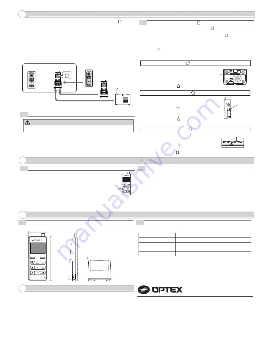
PAIRING WITH OTHER DEVICES
6.
MODEL NAME: OPTEX (IVP-HU) Handheld Monitor Unit
8-1
Dimensions
8-2
Specification Table
(1) In a normal operation mode, press and hold the left function key
for two seconds to enter menu mode.
(2) Select menu number 3 # DEVICES IN NETWORK
by up and down key.
(3) Press LEFT function key to “OK”
(4) The display will show the number of devices in the network.
Confirm number of devices registered with the HOME ID.
(5) Maximum numbers of devices in an system are;
2 IVP-DU, 2 IVP-GU and 4 IVP-HU. Go over pairing procedure unless optimal
numbers of devices are displayed.
One Handheld Monitor Unit (IVP-HU) must be configured to have a HOME ID*1
prior to paring up with other devices.
*1 HOME ID is an unique network identification protocol for system.
One Handheld Monitor Unit can issue the HOME ID and all other devices on
the same system must be assigned the same HOME ID.
WARNING
Any pre-existing HOME ID set up will be cleared out with this procedure.
6-1
How to create HOME ID by a Handheld Monitor Unit
If not purchased in a bundle package, IVP-DU is
in the pairing mode when powered up. IVP-DU
beeps continuously when PUSH button is pressed.
To purposely enter into a paring mode, press PUSH
button once and hold a pairing button in a back.
Once IVP-DU is paired, HU shows “DU# CONNECTED”.
(1) Press “OFF” and then press pairing button in the back of the unit once.
The IVP-HU will be in a pairing mode.
(2) Press the pairing button again and hold until the unit makes a beep sound.
(3) Press “Left function key” on the front to confirm “CREATE.”
Pairing button
7-1
Confirming number of devices in a HOME ID
7-2
Checking operations on Handheld Monitor Unit
(1) Make sure IVP-HU has been charged and there is a green indication on the top
of display.
(2) To confirm RF reception, bring IVP-HU and IVP-DU in a line of sight.
(3) Press “Push button” on a paired Door Camera Unit.
All paired IVP-HUs display an image from the IVP-DU.
(4) Press “Answer” on any of the IVP-HU.
Voice from IVP-HU will be heard from the IVP-DU.
(5) Press “OFF” on the IVP-HU to terminate the communication.
(6) Move IVP-HU (and IVP-DU) to a desired location and repeat (3) to (5)
to confirm reception of signals.
80mm / 3.15”
71mm / 2.8”
Operating Temperature
Dust/Water Protection
Radiowave Frequency
0 to 40 degC (32 to 104 degF)
< 90% RH (no condensation)
N/A (Indoor Use Only)
2.4 GHz
Operating Humidity
Power
Power Adaptor 5.5V DC
Pairing Button
60mm / 2.36”
30mm / 1.18”
145mm / 5.71”
SYSTEM SETUP
1 DATE & TIME
2 SYSTEM CONFIGURATION
3 DEVICES IN NETWORK
4 PC CONNECTION
OK
BACK
Pairing button A
& B
Sound ON/OFF Switch
Use designated battery, IVP-BAT, for IVP-HU.
Please contact your regional technical support for procurement information.
5921603
REV 1.03
OPTEX INC. (U.S.)
URL: http://www.optexamerica.com/
OPTEX DO BRASIL LTDA. (Brazil)
URL: http://www.optex.net/br/es/sec/
OPTEX (EUROPE) LTD. / EMEA HQ (U.K.)
URL: http://www.optexeurope.com/
OPTEX CO., LTD. (JAPAN)
URL: http://www.optex.net/
1. This product is under a warranty for a normal usage for 18 months from the date
of manufacturing. The date of manufacturing can be identified from a LOT number
indicated on a label placed in battery compartment of IVP-HU.
2. The warranty may not be applicable when any of following circumstances is found.
- Mechanical or electrical modification is made to the product and the good’s
appearance indicates an alterations or a significant damage.
- The product is already been diagnosed by someone other than the manufacturer.
- Product malfunction is resulting from an improper usage, an accident,
natural disaster or any environmental event.
- Please call our technical assistance before arranging a return.
LOT: YYWWZ (e.g. LOT 1350Z)
YY indicates last two digits of the year manufactured (e.g. “13” = Year 2013)
WW indicates Xth week of the year manufactured (e.g. “50” = 50th week)
NOTE: An additional Device DU, HU and GU must be paired to HU only:
1
6-2
Handheld Monitor Unit bundled with Door Camera Unit already has a HOME ID
set and paired to each other.
IVP-DU
IVP-HU
IVP-DU
IVP-HU
IVP-GU
Exsiting
System
1
How to enroll HU, DU and GU to HU 1
(1) Press pairing button twice in the back of IVP-HU .
The unit will be in “PAIRING MODE”.
(2) Proceed to “SCAN” by pressing “Left function key”. IVP-HU starts scanning
for other devices for 60 seconds.
(3) Prepare other device into their pairing mode. (REF as follows)
When the device is ready, the new unit will be enrolled to the HOME ID and
IVP-HU shows which device was connected.
(4) If another device needs to be enrolled, re-enter “SCAN” by “Left Function key”
and repeat the process.
1
1
1
IVP-DU: Door Camera Unit to HU 1
IVP-HU: Handheld Monitor Unit to HU 1
IVP-GU: Gateway Chime Unit to HU 1
1
If not purchased in a bundle package, by the factory
default, IVP-GU is in the pairing mode when powered up.
IVP-GU beeps continuously and green/red LED blinks.
Press down both A and B buttons while powering up
the Gateway Chime Unit to enter the pairing mode.
Once IVP-GU is paired, HU shows “GW CONNECTED”.
1
If not purchased in a bundle package, IVP-HU is in the
pairing mode when powered up. Choose “JOIN” by
“Right function key” to enroll into an existing HOME ID.
Once IVP-HU is paired, HU shows “HU# CONNECTED”.
If otherwise, follow the instruction 6-1 to create
a new HOME ID. After an enrollment of new HU,
reset a Time & Date on HU to reflect the setting
onto the added HU unit.
1
1


