background image


EcoOnline Perf

™ 

Solar Pool Heating System  --  Installation & User Manual  

© Copyright 2020 Optex Solar Pty Ltd. All rights strictly reserved. 


Page 51


27


Optimizing Collector Pressure 

27.1


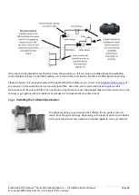
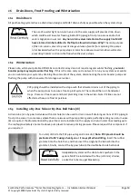
Installing the Pressure Gauge 


The pressure gauge

 must be installed on the return line preferably near eye level.

 Drill 

into the PVC pipe using an 8.5mm drill. Insert the rubber grommet into the hole 
tapered end first. Use pink Teflon tape on brass tread, lubricate the brass barb with 
silicon spray prior to insertion into the grommet. 

Note: PVC plastic should be 

preheated to 50

˚C using a heat gun 

or it may split when drilling. 


27.2


Pressure Check Procedure 

To make pressure adjustment depending on over-pressure or under-pressure situations, 

you’ll need to install either 

a ball by-pass valve (18) to reduce pressure or a ball break valve (16) on the return line to increase back pressure 
(both at near ground level for easy adjustment). Manual type systems need only the adjustable 3-way ball valve. 
Collector pressures can then be adjusted as follow:  


Summary of Contents for EcoOnline Performance+

Page 1: ...wise without the specific written permission of Optex Solar Pty Ltd Trademarks appearing in this manual are the sole property of Optex Solar Pty Ltd or their respective owners Nothing in this publicat...

Page 2: ...12 Additional Required Components Not Supplied 13 Required Tools 14 Safety When Working at Heights 14 1 Ladder Safety 15 Choosing a Place to Install the Collector Array 16 Collector Water Flow Config...

Page 3: ...xings 20 Tile Roof Aluminium Angle Mounting Options 20 1 Top Panel Tile Attachment 20 2 Two Row Panel to Panel Attachment 20 3 Two Row Mid Array Panel Attachment 20 4 Bottom Panel Tile Attachment 20 5...

Page 4: ...1 Installing the Roof Hot Sensor 25 2 Installing the Pool Cold Sensor 25 3 Extending Sensor Cords 26 Drain Down Frost Proofing and Winterization 26 1 Drain Down 26 2 Winterization 26 3 Installing a B...

Page 5: ...lease note EcoOnline has a strong product safety policy do not install products without reading safety guidelines in the manual Please report any product safety issues or near misses to info EcoOnline...

Page 6: ...present this collector array system is not recommended for installations in cyclonic regions C or D or on houses situated on top of hills exposed to strong winds or on second story or higher roofs Ins...

Page 7: ...heating sizing calculator www EcoOnline com au pool water temperature simulator 5 1 A Word on Transparent Bubble Pool Covers EcoOnline recently carried out a full pool heating loading technical study...

Page 8: ...teractive pump sizing simulator which can be found on our website at www EcoOnline com au oku performance pool heating pump sizing However if you go with a lower power pump you ll need the following A...

Page 9: ...ook it up from the table supplied below based on the total water area and average depth 7 2 Solar Pump Sizing for Booster Systems Pool Water area vs Average Depth Conversion Table Average depth Waters...

Page 10: ...g System Lines Anticipated Flow Rate Absolute Minimum Ideal PVC Pipe Size Maximum Pipe Size 70 Litres min 20 PVC DN20 25 PVC DN25 32 PVC DN30 120 Litres min 25 PVC DN25 32 PVC DN30 40 PVC DN40 200 Lit...

Page 11: ...of the installed collector and the valley points of the roof corrugations should be no greater than approximately 40mm 2 Panels should have adequate clearance from roof edges 3 Panels on roofs MUST N...

Page 12: ...2 40mm ID reinforced silicon joiners 4 Stainless steel hose clamps 6 316 Stainless steel straps black 1 25cm length perforated 316 stainless band 1 40mm ID reinforced silicon joiner 1 25mm ID reinforc...

Page 13: ...drill bits Power Lead Heat Gun Tape measure Tin snips Industrial Ladder Needle nose pliers Power Lead A single 32 PVC or 20 PVC Socket for heat smoothing any misshapen barbs see below Roof Mounting S...

Page 14: ...be securely anchored at the base and secured at the top to prevent slipping WHEN WORKING AT HEIGHTS SAFETY COMES FIRST A person can easily fall off a ladder or roof and be seriously injured For instal...

Page 15: ...nstallation User Manual Copyright 2020 Optex Solar Pty Ltd All rights strictly reserved Page 15 Solar panels should not be mounted in windy or gusty conditions a panel can easily be caught in the wind...

Page 16: ...ment The Building Commission or SPASA for details regarding pool safety barriers in your state Please keep up to date with regulations as they change over time For more information see AUSTRALIAN STAN...

Page 17: ...anual Copyright 2020 Optex Solar Pty Ltd All rights strictly reserved Page 17 16 Collector Water Flow Configurations 16 1 Dual Header Panel Single Row Flow Configuration 16 2 Supply and Return Plumbin...

Page 18: ...entine 17 4 Max 100L min 20 Panels Splits flow lower panel pressures Higher panel pressures Harder to plumb more PVC bits Easier to plumb but headers must be level Better for larger panel per row arra...

Page 19: ...connect Panel Flow Configuration 16 8 Three Row In Parallel Flow Configuration Please note the bottom row of panels in a three row or more configuration installed on a roof pitch greater than 15 will...

Page 20: ...ormance Solar Pool Heating System Installation User Manual Copyright 2020 Optex Solar Pty Ltd All rights strictly reserved Page 20 16 9 Staggered Array Flow Configurations 16 10 Level Ground Mounting...

Page 21: ...he effectiveness of a pool or spa Child Safety Barrier Split collector arrays with a vertical height difference no more than 1m can use the above configuration Both array should be installed facing th...

Page 22: ...r Low Pitch Roof 16 14 Preferred Bi Directional Flow Configuration Split collector arrays with a vertical height difference of greater than 1m MUST use the above configuration with a constricting ball...

Page 23: ...on Frost Areas Collector arrays that face opposing compass directions are not recommended unless the roof pitch is less than 15 In this case the temperature sensor should be installed at an angle that...

Page 24: ...ights strictly reserved Page 24 16 16 Top Feed Flow Configuration for Frost Areas 16 17 Plumbing Flow Configurations Not Recommended For frost prone areas the supply and return lines that runs over th...

Page 25: ...lope toward the outlet to make sure all air is automatically removed from the entire array upon filling This is especially important for system with row containing 10 or more panels The vacuum release...

Page 26: ...ner and not on the connector barbs HAND TIGHTEN ONLY using with an 8mm hex socket Do not glue in silicon joiners Pinhole leaks can be sealed with a little silicon You may need to slightly re tighten t...

Page 27: ...ns must account for an ultimate contraction of 22mm in length per panel Key design principles when choosing a roof mounting means 1 Consider the high thermal contraction of HDPE 2 Panels should be as...

Page 28: ...llation User Manual Copyright 2020 Optex Solar Pty Ltd All rights strictly reserved Page 28 19 1 Single or Multi Row Metal Roof Fixings Wind Region A For row arrays exceeding 15 panels per row expansi...

Page 29: ...29 19 2 Single or Multi Row Metal Roof Fixings for Wind Regions B C NOTE For single or multi row arrays in wind regions B or C aluminium L angle MUST be installed for top and bottom of each row Mid pa...

Page 30: ...ights strictly reserved Page 30 19 3 Single or Multi Row Tile Roof Fixings for Wind Region A B For single or multi row arrays in wind regions B aluminium L angle MUST be run for the top and bottom of...

Page 31: ...s We also highly recommend you season the panels before installation to removed some of the permanent contraction the panels are prone to Seasoning the panels involves laying the panels out in the sun...

Page 32: ...ree or more rows must have a pair of aluminium L angles top and bottom for each row of collectors or at least for each pair of rows to allow for contraction IMPORTANT DO NOT over tighten stainless ste...

Page 33: ...e recommend using a minimum roof hook spacing of 600mm in the top and bottom row Depending on your wind loading see Wind Proofing section angle of install you may require a higher density of roof hook...

Page 34: ...l Heating System Installation User Manual Copyright 2020 Optex Solar Pty Ltd All rights strictly reserved Page 34 20 2 Two Row Panel to Panel Attachment 20 3 Two Row Mid Array Panel Attachment Region...

Page 35: ...formance Solar Pool Heating System Installation User Manual Copyright 2020 Optex Solar Pty Ltd All rights strictly reserved Page 35 20 4 Bottom Panel Tile Attachment 20 5 Stainless Steel Cable Anchor...

Page 36: ...Point 21 Corrugated Metal Roof Mounting Options 21 1 Mounting Options for Top or Bottom Angle Rail For metal roofs we recommend using a minimum screw fixing space of 600mm when fixing the aluminium an...

Page 37: ...ce Solar Pool Heating System Installation User Manual Copyright 2020 Optex Solar Pty Ltd All rights strictly reserved Page 37 21 2 Thermal Expansion Gaps for Aluminium Channels 21 3 Metal Roof Screw S...

Page 38: ...Loadings Per Panel in Wind Region A Kg Region A 10 Roof Pitch 12 5 Roof Pitch 15 Roof Pitch 17 5 Roof Pitch 20 Roof Pitch Terrain Category 1 120 Kg 110 Kg 95 Kg 90 Kg 80 Kg Terrain Category 2 100 Kg 9...

Page 39: ...and cleared subdivisions with isolated trees Terrain Category 2 5 Averaged intermediate between Terrain Category 2 and Terrain Category 3 Terrain Category 3 Numerous closely spaced building obstructi...

Page 40: ...de line is not required but still recommended Greater than 70Kg per panel Stainless guide line is required across each row Greater than 120kg per panel Stainless guide line is required with in between...

Page 41: ...ith 6 or less panels in one row as the straps supplied can accommodate these thermal changes for other arrays please follow the below procedures 23 1 Mounting Procedure for Arrays 10 or Less Panels pe...

Page 42: ...ure Optimization section below and never hot panels Why Applying straps clamps to hot panels can cause issues for large arrays when the collector array contracts significantly in the cool of the night...

Page 43: ...oOnline com au for special expansion joiners if you need to run your array with greater than 15 panels per row Arrays containing more than 16 20 panels in a row should only be installed with 25mm PVC...

Page 44: ...small solar pump runs independent of the large main filter pump Requires separate solar suction provisions to be installed When installing PVC lines attention should be given to the minimum spacing fo...

Page 45: ...n tees above or only just below the water line will require regular maintenance of non return valves 24 3 Notes on Teeing into the Suction Line for Configuration 2 Filter pump must be set on a timer t...

Page 46: ...rubber seat contact us at info ecoonline com au if you require it A standard flap non return will not suffice Also note such a system will need regular careful maintenance of the solar and filter lin...

Page 47: ...ectors Large main filter pump needs to run all day for solar Can be retrofitted to pools that don t have separate solar provisions Motorized three way valve and controller can be retrofitted later Req...

Page 48: ...Advantages Disadvantages Less extra plumbing is required for solar Requires second pump and special controller Only filtered water runs through collectors Does not require separate solar suction provi...

Page 49: ...his you will need to drill a hole in the suction line please check the controller manual for the recommended size 25 3 Extending Sensor Cords The sensor cords can be extended using a similar type cord...

Page 50: ...iming pressure Please request this component if you require it To install drill into the PVC pipe using an 8 5mm drill Note PVC plastic should be preheated to 50 C using a heat gun or it may split whe...

Page 51: ...on tape on brass tread lubricate the brass barb with silicon spray prior to insertion into the grommet Note PVC plastic should be preheated to 50 C using a heat gun or it may split when drilling 27 2...

Page 52: ...n line using the ball valve brake 16 see plumbing diagrams lever handle by a small increment 2 If after some time the air bubbling continues constrict flow by another small increment 3 If air bubbles...

Page 53: ...h as eyeballs in the return outlets 2 If pressure is still too great as measured at the pressure gauge see above Pressure Check Procedure install a by pass ball valve 18 see plumbing diagrams 3 Turn t...

Page 54: ...elease valve 7 is a critical system component It should be checked that it is not weeping corrosive water onto the roof X Non Return Valve The non return valve 8 see plumbing diagrams is a critical sy...

Page 55: ...with sufficient play to allow for collector contraction Ultimate uplift wind loadings were considered and panels secured appropriately A hot spot check was performed All collectors are cool during ful...

Reviews: