


2. Attach RPi to OSPi
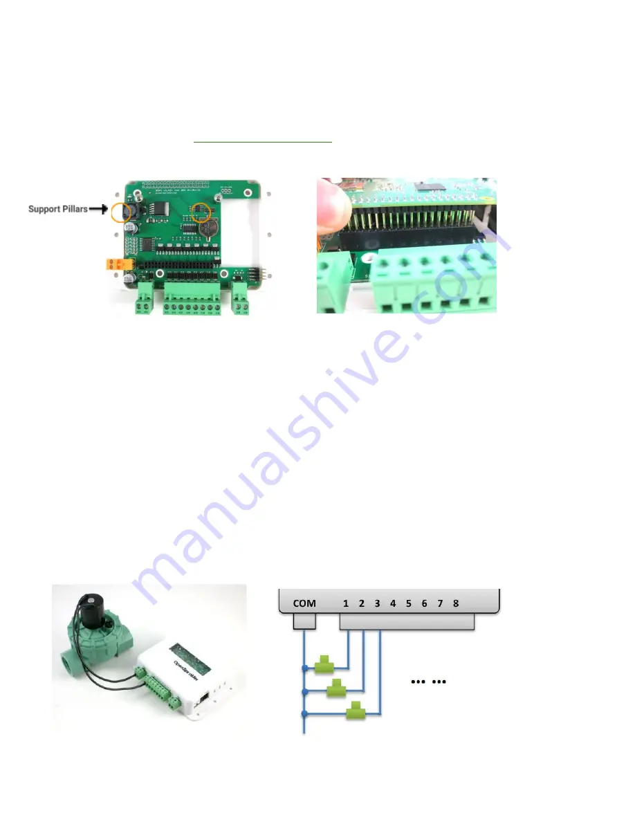
OSPi has two support pillars (positions marked in the left image below) that match the screw holes on RPi (except RPi 0
which doesn't have these screw holes). First, install the support pillars to the OSPi board (note: in some kits these
support pillars are replaced by 3D printed version, in which case just plug those in firmly into the OSPi board); then, plug
RPi into OSPi through the 2x20 pin headers, with SD card slot facing the left, and USB and Ethernet jack facing the right.
Double check the orientation and make sure all pins are aligned
. Any misalignment may result in damage to RPi. The two
screw holes should also match the support pillars. Insert RPi all the way to the end. The USB and Ethernet connector
should go through the cutouts on the PCB.
3. Web Connectivity
OSPi fits a nano-size USB WiFi dongle. You can insert the dongle into any of the available RPi USB ports. If you prefer
wired connection, note that there is no special cutout for the Ethernet cable, you can take out one side panel of the
laser-cut acrylic enclosure, or alternatively use a Dremel to make a cutout yourself, in order to allow Ethernet cable to pass
through.
If you use RPi 3 or 4 and notice dropped performance of built-in WiFi, you probably need to use a separate USB power
adapter to power it directly from its microUSB port. You can take out one of the side panels to allow the microUSB cable
to pass through.
4. Wiring Sprinkler Valves
To connect a sprinkler valve, insert one wire to the COM (common) terminal, and the other wire to any of the station
terminals (1-8). The COM terminal has two ports – they are internally connected so either port is fine. To connect multiple
valves, one wire from each valve should come together and go to the COM terminal; and the other wire from each valve
goes to an individual station terminal. See the diagram below.


