HOBO Temp/RH 2.5% Data Logger (UX100-011) Manual
1-800-LOGGERS 7
www.onsetcomp.com
Internal Event Name
Definition
New Interval
The logger has entered or exited burst
logging mode.
Safe Shutdown
The battery level dropped below 2.5 V; the
logger performs a safe shutdown.
Mounting the Logger
There are several ways to mount the logger using the materials
included:
•
Use the four built-in magnets on the back of the logger to
mount it to a magnetic surface.
•
Attach the Command strip to the back of the logger to
mount it a wall or other flat surface.
•
Use the double-sided tape to affix the logger to a surface.
•
Insert the hook-and-loop strap through the mounting
loops on both sides of the logger to mount it to a curved
surface, such as a pipe or tubing.
Protecting the Logger
The logger is designed for indoor use and can be permanently
damaged by corrosion if it gets wet. Protect it from
condensation. If the message FAIL CLK appears on the LCD
screen, there was a failure with the internal logger clock
possibly due to condensation. Remove the battery immediately
and dry the circuit board.
Note:
Static electricity may cause the logger to stop logging.
The logger has been tested to 8 KV, but avoid electrostatic
discharge by grounding yourself to protect the logger. For more
information, search for “static discharge” in the FAQ section on
onsetcomp.com.
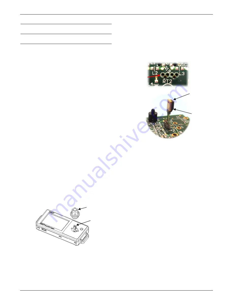
Replacing the RH Sensor
The internal RH sensor may require replacement if it is
damaged mechanically or by exposure to condensation or
chemicals. The replacement sensor (HUM-RHPCB-3A) is
available from Onset. To replace the sensor:
1.
Remove the cap from the logger case with a one quarter
turn counter-clockwise.
2.
Remove the RH sensor from the board inside the logger
case and discard it.
3.
Touching only the sides of the RH sensor (not the black part
of the sensor), carefully insert each of the four pins into the
four holes in between the L2 and L3 markings on the board
(shown here enlarged and without the logger case for
illustrative purposes). Hold the sensor at a slight angle as
you are inserting it and let the pins come to rest inside the
holes. The sensor should remain upright when positioned
properly in the four holes. Use a magnifying glass or bright
light to see the board details if necessary. Note that the
black part of the sensor should be facing forward as shown
in the diagram with step 1.
4.
Once the sensor is in position, gently push down until it is
firmly in place.
5.
Place the cap over the RH sensor lining up the notches on
the cap with the grooves on both sides of the sensor.
Secure the cap with a one quarter turn clockwise until it
snaps back in place.
6.
Check logger status in HOBOware to verify the RH reading.
Battery Information
The logger contains a 3V CR2032 battery (HRB-TEMP). Expected
battery life varies based on the ambient temperature where
the logger is deployed, the logging or sampling interval,
frequency of offloading to the computer, number of channels
that are active, if burst or statistics logging modes are active,
and battery performance. A new battery typically lasts 1 year
with logging intervals greater than 1 minute. Deployments in
extremely cold or hot temperatures, a logging interval faster
than 1 minute, or a sampling interval faster than 15 seconds
can impact battery life. Estimates are not guaranteed due to
uncertainties in initial battery conditions and operating
environment.
The logger can also be powered by the USB cable when the
remaining battery voltage is too low for it to continue logging.
Connect the logger to the computer, click the Readout button
on the toolbar, and save the data as prompted. Replace the
battery before launching the logger again.
Cap
RH Sensor, with
black part of
sensor facing
forward
Insert the RH
sensor in the four
holes between L2
and L3
WARNING:
Touch the
sides of the sensor only;
DO NOT touch the actual
sensor (the black chip)
shown here. Doing so may
compromise accuracy
The black part of the
sensor should be
facing forward


