


HOBO U30 Station (NRC) User’s Guide
3
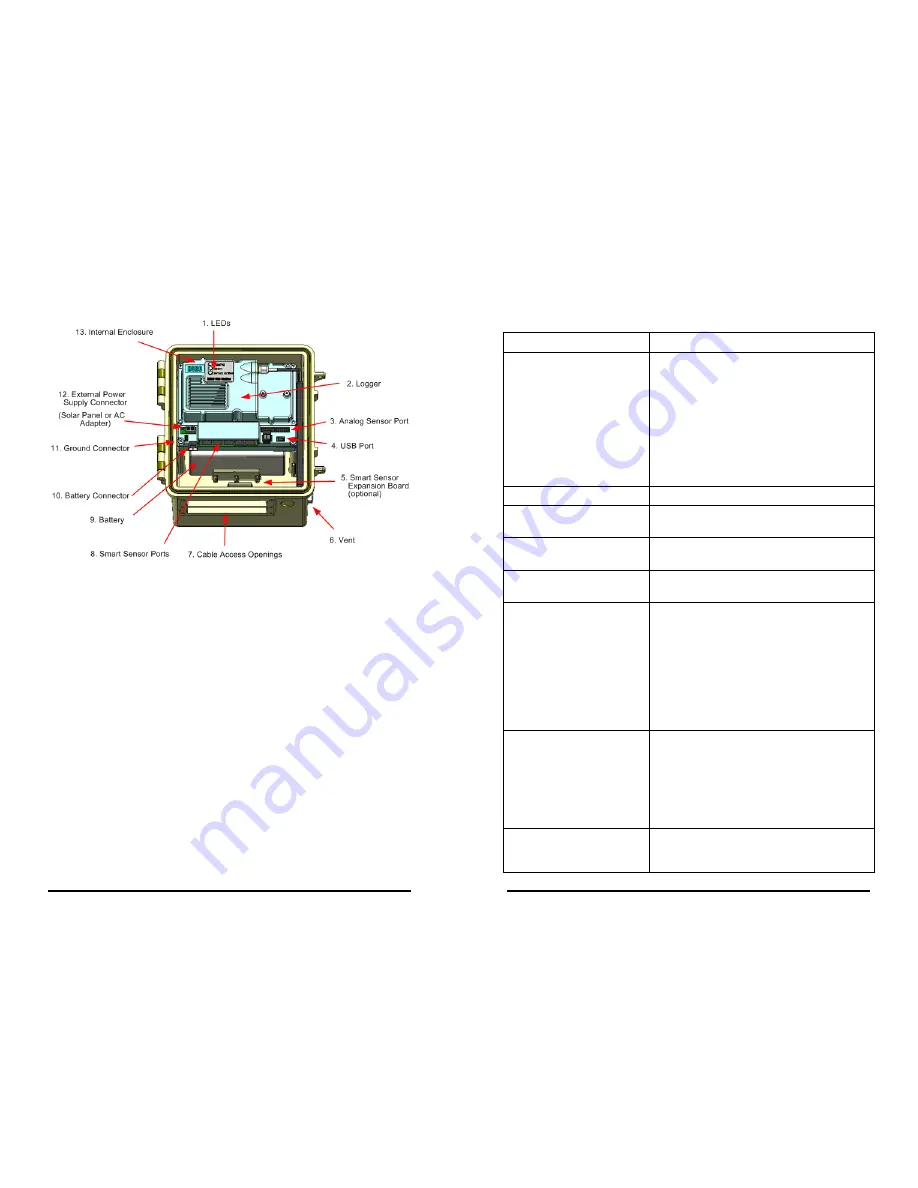
HOBO U30 NRC Station Components
U30 NRC Components
4
HOBO U30 Station (NRC) User’s Guide
Component Descriptions
Item Description
1. LED
There are three Light Emitting Diode (LED)
status indicators.
Logging indicates whether the system is
currently logging.
Alarm indicates if an alarm has been tripped.
Sensor active indicates that Smart Sensor
network communications are occurring.
For more information see LED Descriptions
on page 51.
2. Logger
The U30 sits inside the outer case.
3. Analog Sensor Port
This connector is where the optional Analog
Sensor Port is factory-installed.
4. USB port
Plug in a USB cable here to connect directly
to a computer.
5. Smart Sensor Expansion
Board
6. Vent
This vent allows pressure to equalize inside
the enclosure, but does not allow liquid to
pass through.
NOTE
: The pressure inside the case does not
match the outside air pressure exactly so a
barometric pressure sensor deployed within
this case cannot measure the true
atmospheric pressure unless it has its own
unrestricted vent to the outside.
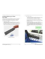
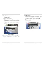
7. Cable access openings
All cables and wires are routed through a
protective rubber cable channel placed in this
opening. If you are using the optional
expander board for additional Smart Sensors,
you will need to use both cable access
openings. See Accessing the Secondary
Cable on page 65.
8. Smart Sensor ports
Connect up to five Smart Sensors in these
RJ-12 jacks. Use one port to connect the
optional expander board for additional Smart


