background image


16

CONNECTING THE RAID SYSTEM TO A 
COMPUTER 


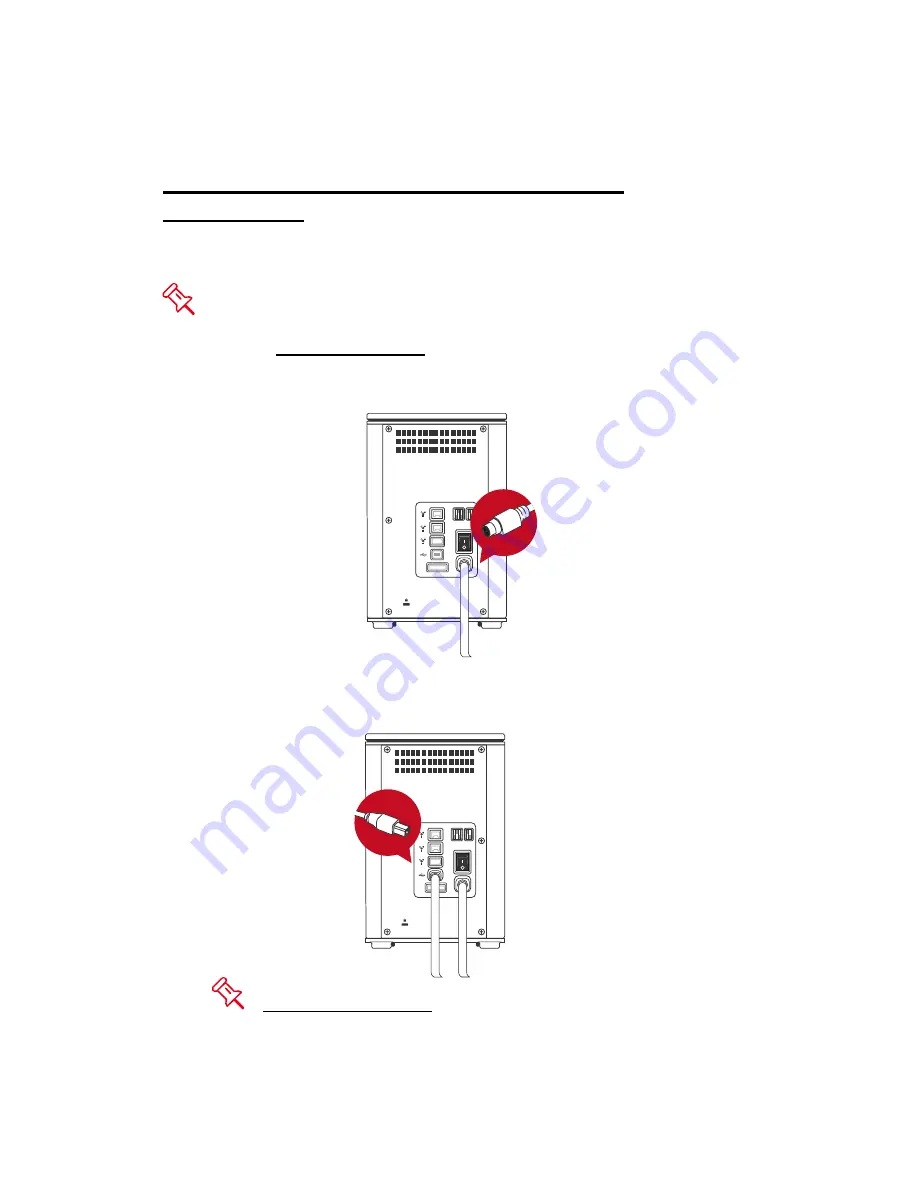
Complete the following steps to connect the RAID System to a host computer. 
 

 The RAID System should only be connected to a host computer via one 

interface.  Connection of the system to a computer via two or more interfaces 
simultaneously is not recommended. 
 

1.  Connect the AC/DC power adapter. 


eS

A

T

A

D

C

 IN

RA

ID

HD


2.  Insert both ends of the USB 2.0, eSATA, FireWire 400, or Fire Wire 800 

cable(s) into the corresponding port of the RAID System and the host. 


eS

A

T

A

DC

 I

N

RA

ID

HD


 It is highly recommended to select only one interface to do data 

transfer.  

Summary of Contents for RS-M4QO

Page 1: ...1 2010 07 29 Ver08 ...

Page 2: ...RAID SYSTEM 10 CONNECTING THE RAID SYSTEM TO A COMPUTER 16 CONNECTING MULTIPLE DEVICES 18 RAID MODES 19 RAID MODE COMPARISON LIST 19 RAID 0 STRIPING 20 RAID 1 MIRRORING 21 RAID 5 22 RAID 5 HOTSPARE 23 RAID 0 1 24 SETTING CHANGING THE RAID MODE NUMBER OF HDDS MANUALLY 25 RAID SWITCH 27 HD SWITCH 27 NUMBER OF DISKS SUPPORTING EACH RAID MODE 28 HDD SLOT NUMBER 28 HDD ALLOCATION 29 LED INDICATORS 30 P...

Page 3: ...33 DRIVER INSTALLATION 34 VERIFY DRIVER INSTALLATION 34 Mac OS 34 Windows OS 34 Windows 2003 and XP 35 Windows 2000 35 Q AS 36 GENERAL 36 HDD CAPACITY 36 DISCREPANCY IN REPORTED ACTUAL SIZE CAPACITY 37 HDD ALLOCATION 37 RAID 0 38 RAID 1 38 RAID 5 38 RAID 5 HOTSPARE 38 RAID 0 1 39 REBUILD 39 APPENDIX SPECIFICATIONS 40 ...

Page 4: ...nterference This device must accept any interference received including interference that may cause undesired operation This equipment has been tested and found to comply with the limits for a Class B digital device pursuant to Part 15 of the FCC rules These limits are designed to provide reasonable protection against harmful interference when the equipment is operated in a commercial environment ...

Page 5: ...rface and avoid all dramatic movement vibration and percussion Do NOT allow water to enter the RAID System unit Installation of additional equipment in the host computer may be required Visit our website to download the latest product information updates Do NOT attempt to service this unit yourself Disassembling the RAID System unit s inner parts will expose you to dangerous voltages or other haza...

Page 6: ...ID 0 1 Configures RAID modes easily using switches no IT expertise required Simplifies RAID management no software installation required Monitors system status via LED indicators Prevents over tightened HDDs with auto limiting segmented screws Features a trayless function with the SmartGuider and user friendly design enables effortless HDD hot swapping Dissipates heat efficiently with aluminum hou...

Page 7: ...ac OS X 10 4 Intel or higher One available eSATA port USB 2 0 IEEE 1394a or IEEE 1394b port Depends on model 3 5 SATA compatible hard drive is required for the RAID System unit Once the HDDs are formatted the actual available storage capacity can vary depending on the selected operating environment normally 5 10 less Optional Accessories eSATA PCI PCI X or PCI Express Card Package Contents USB Typ...

Page 8: ...VIEWS Front View Rear View eSATA DC IN RAID HD 2 FireWire 800 2 ports 6 RAID Mode Switch 3 FireWire 400 4 USB 2 0 Type B 5 eSATA Port 7 HD Switch 8 Power Switch 9 DC IN 10 Lock Port Slot The status indication of each LED indicator is listed under the LED INDICATORS section ...

Page 9: ...9 Top Cover View Exposed FRONT Indicator 4 Spare HDD Screws 1 1 1 2 HDD Slots indicate HDD 1 through HDD 4 1 3 1 2 3 4 1 4 Handles ...

Page 10: ... on the back edge of the top lid Simultaneously push the lid in the direction away from you front to back using your thumbs A click sound would indicate the release of the top lid security clasp 2 Lift the top lid up to remove and expose the top view or HDD slots Take out the handles from the enclosure itself and locate the HDD screws in the packaging box ...

Page 11: ...the metal cover side facing up and ensure that the interface connectors are oriented toward your left side Connectors 4 Position the handle to the HDD end which is facing away from the interface connectors and align it with the screw hole openings Connectors ...

Page 12: ... onto the HDD by inserting and tightening the screws the left one first then the right one Left Right 6 Now flip the HDD so it is facing you with the PCBA Printed Circuit Board on top and the unfasten handle side facing you ...

Page 13: ...ndle to make sure that the holes glide smoothly on the screw guides Repeat the same procedures for the rest of HDDs The auto limiting segmented screws are designed to prevent the HDDs or and the handles from damages due to over tightening Furthermore this design makes the handle slide easily without any tightness ...

Page 14: ...e SmartGuider System won t be able to align and the HDD cannot be inserted 10 Align the handle with the guide rails and slide the HDD into the indicated slot Firmly push downward until a thump sound is heard Repeat the same procedures for the rest of HDDs In most cases you would need to firmly push the trays to a close until a thump sound is heard ...

Page 15: ...one hand on the front edge and one on the back edge of the top lid Simultaneously push the lid firmly downward and toward you back to front A click sound would indicate grasp of the top lid security clasp 12 Now the RAID System is ready for connection to a computer Installing HDDs OK ...

Page 16: ...erface Connection of the system to a computer via two or more interfaces simultaneously is not recommended 1 Connect the AC DC power adapter eSATA DC IN RAID HD 2 Insert both ends of the USB 2 0 eSATA FireWire 400 or Fire Wire 800 cable s into the corresponding port of the RAID System and the host eSATA DC IN RAID HD It is highly recommended to select only one interface to do data transfer ...

Page 17: ...e Power LED light will become steadily green and the HDD LED lights will become white and blink about 15 seconds If the HDDs are inside the RAID System the HDD LED lights will remain steadily white If there are no HDDs inside the RAID System the HDD LED lights will turn off after blinking ...

Page 18: ...e RAID System may be such as digital video camera another HDD DVD writer and much more However you must use the same interface in order for the Daisy Chain to work The computer will not recognize different interfaces if they are all used at the same time In addition if a mix of connections is used the resulting speed will be limited to the lowest one available When an additional FireWire connector...

Page 19: ... or more of increased data integrity fault tolerance throughput or capacity when compared to single drives Deleting the current partition prior to changing RAID modes is highly recommended Using identical HDDs with the same capacity and RPM and from the same manufacturer are highly recommended for best capacity utilization RAID Mode Comparison List RAID mode RAID 0 Striping RAID 1 Mirroring RAID 5...

Page 20: ...mented simple configuration Striping should never be used for mission critical applications The speed of operation is excellent in comparison to other RAID modes In Striping mode it is not possible to see the HDDs as more than one unit If you choose to insert all 4 HDDs it will still be viewed as one single storage unit When you choose to insert only two HDDs there is not limitation on the order o...

Page 21: ...ce HDD the target HDD should then be inserted in the other HDD tray The RAID System will then recognize the target HDD the rebuild process will begin when the HDD LED starts blinking In Mirroring mode only 2 HDDs are allowed for the function to perform properly There is no limitation on the order of insertion or the slot number However if all 4 HDDs are inserted the RAID System can only do Mirrori...

Page 22: ...de the parity block is not the identical copy of the source data It is generated via parity calculation RAID 5 mode provides decent data protection and fault tolerance The speed of operation is average in comparison to other RAID modes The number of disks supported by RAID 5 is 3 or 4 The storage capacity will become all disks in total but minus 1 The capacity is limited to the size of the smalles...

Page 23: ...low in comparison to other RAID modes Under the RAID 5 HotSpare mode 4 HDDs in an array are required The storage capacity will become 3 minus 1 totaling only 2 HDD storing capacity But it is limited to the smallest size of HDDs plus 1 more HDD as the backup disk RAID 5 HotSpare Disk 1 Disk 2 Disk 3 Disk 4 A1 A2 B1 Bp Cp C1 D2 Dp Ap B2 C2 D1 Spare If one of the disks fails the source data can be re...

Page 24: ...ept in RAID 0 Under the RAID 0 1 mode 4 HDDs in an array are required However the storage capacity is only as 2 HDDs which the total will be based on the smallest size of the HDDs RAID 1 RAID 0 1 RAID 0 RAID 0 Disk 1 Disk 2 Disk 3 Disk 4 A1 A3 B1 B3 A2 A4 B2 B4 A1 A3 B1 B3 A2 A4 B2 B4 In RAID 0 1 mode if any 2 of the 4 disks fail at the same time the data can still be reconstructed when they are r...

Page 25: ... Mode deletes all data stored on the device If you have saved data in the drives backup all data before changing the RAID Mode 1 Power off the RAID System eSATA DC IN RAID HD OFF 2 Use a small flat blade screwdriver to select the RAID mode RAID Switch eSATA DC IN RAID HD RAID ...

Page 26: ...C IN RAID HD HD 4 After setting the new RAID mode and the number of HDDs power the RAID System on eSATA DC IN RAID HD ON It is highly recommended to always power off the RAID System before setting or changing the RAID Mode Switch and the HD Switch to ensure the new changes are accepted by the System ...

Page 27: ...Switch 2 4 3 4 HotSpare Disk Number Setting If the HD Switch setting is not supported by the RAID mode desired or the number of disk inserted is not the same as recommended the RAID System cannot be created successfully and the RAID Alert LED will be on Please see more explanation in the LED INDICATORS section ...

Page 28: ...f Disk in RAID RAID 0 Striping 2 or 4 RAID 1 Mirroring 2 RAID 5 3 or 4 RAID 5 HotSpare 4 RAID 0 1 4 HDD SLOT NUMBER 1 2 3 4 It is highly recommended to place the HDDs into the RAID System in order from 1 through 4 consistently starting with slot 1 indicated as HDD 1 ...

Page 29: ...n the package to help identify the HDD allocation Although the HDD slots can help with organization when the hard disks are pull out without remembering their arrangement order the data may be lost if the HDD allocation is not the same as the one originally set in the RAID System 1 1 ...

Page 30: ...the disks is not working properly or fails the LED indicator will blink and remind you to take actions Those actions may include replacing a healthy HDD Error The RAID Alert LED will be on in RED if RAID status is in error When the number of disk set is not supported by certain RAID mode or the number of disk inserted is not the same as HDD Switch setting RAID cannot be created successfully HDD LE...

Page 31: ...ifference between a flashing LED and a blinking LED is that flashing refers to the read write activity and blinking refers to slow but regular pulses SAFE REMOVAL OF THE RAID SYSTEM Safe removal of the Enclosure from the host controller is highly recommended especially when switching interfaces In order to safely remove your Enclosure from the host controller you would need to eject the device on ...

Page 32: ... Yes No If the computer does not come with eSATA interface and an optional eSATA card is added choosing the card that comes with the built in driver in the operation system is highly recommended Disk Volume Over 2TB The 2 TB HDD support is determined by the chipset used in the device and the operating system itself The RAID System supports and recognizes 2 TB HDDs but the actual 2 TB support will ...

Page 33: ...s Windows 2000 or later 32 bit 64 bit OS Mac OS 10 4 x or later An available PCI Express slot CD ROM or DVD ROM drive Hardware Installation 1 Power off and unplug your computer 2 Remove the housing of your computer and locate an available PCI Express slot on your motherboard 3 Insert the card in the available PCI Express slot Ensure that the card is firmly seated in the slot 4 Replace the housing ...

Page 34: ...provided instructions to complete the driver installation Please refer to User s Manual under eSATA Host Card section on our website Verify Driver Installation Mac OS If a driver installation failure error message appears after restarting the computer follow the recommendations provided in the error message Windows OS 1 Right click the My Computer icon on your desktop and choose Manage from the po...

Page 35: ...35 Windows 2003 and XP Windows 2000 ...

Page 36: ...l Lastly if the work requires instant and continuous backup of data such as for a writer or editor then RAID 0 1 would be the best choice since it can provide both high data protection and speed with less storage capacity HDD Capacity Q All my HDDs are at least 1TB or above will the RAID System be able to support the gigantic storage capacity A Yes the RAID System will be able to support any HDDs ...

Page 37: ...mal The surprising fact is that even though it seems like you will have more bytes under Binary the Decimal calculation system actually presents a greater storage capacity More description on capacity issues can be found at the Seagate website under FAQs http www seagate com ww v index jsp locale en US name Storage_Capacity_Measurement_Standards_ _Seagate_Technology vgnextoid 9493781e73d5d010VgnVC...

Page 38: ...me RAID 5 Q If I have inserted 4 HDDs set the RAID Switch at RAID 5 but have the HD Switch set at 3 HDDs Will this work A Yes you may do so but the RAID System will automatically reset the RAID mode to RAID 5 HotSpare The RAID System is created to determine first on the number of HDDs inserted into the System then the RAID mode setting Occasionally the System will still reflect a healthy status ev...

Page 39: ... ones Rebuild Q Does the RAID System have to be connected to the host computer when it is in rebuild mode A No it does not have to be The RAID System can support offline rebuild which means it can perform the rebuild function without being connected to a host computer JBOD Q I have 4 HDDs Can I use them as separate HDDs on the RAID System A No the RAID System does not support the JBOD Just a Bunch...

Page 40: ... 0 1 Data Transfer Speed eSATA up to 3Gbit sec USB 2 0 up to 480Mbit sec 1394a up to 400Mbit sec 1394b up to 800Mbit sec System Material Aluminum case with plastic parts LED Indicators Power Connection Health Access Rebuild RAID Alert Power Supply Input AC 90 264V Output DC 12V 5A Peak current 12A FAN Dimension 80 x 80 x 10 mm x 2 Speed 1900 R P M 10 Noise 17 13 dB A max Dimension 210 L x 138 W x ...

Reviews: