background image

Version 02 


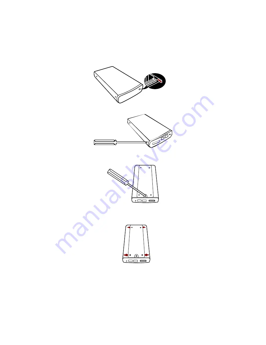
8)  Ensure that the LED indicator is properly aligned with the opening on the 

front panel of the enclosure.  


9)  Reassemble the enclosure by replacing the (2) screws removed in step 1.  


10) Fasten the last (1) screw to reattach the bottom panel.  


11) Attach the four (4) footpads included in the package to the bottom of the 

enclosure. 


Summary of Contents for 2.5" SATA HDD Enclosure

Page 1: ...product information provided in this manual is subject to change without prior notice and does not represent a commitment on the part of the vendor The vendor assumes no liability or responsibility f...

Page 2: ...Enclosure User s Manual Introduction 3 Important Reminders for all Enclosures 3 Getting Started 4 System Requirements 4 Installing the 2 5 SATA HDD 5 Connecting the Enclosure to a Computer 9 Notices...

Page 3: ...ooth flat surface and avoid all dramatic movement vibration and percussion Do NOT allow water to enter the HDD enclosure Avoid placing the HDD enclosure close to magnetic devices such as a mobile phon...

Page 4: ...0 Model Rear Panel Package Content Enclosure x 1 USB cable x 1 IEEE1394a cable x 1 eSATA cable x 1 Quick Start Guide HDD Fastening Screws x 4 Rubber Footpads x 8 AC Power Adapter System Requirements P...

Page 5: ...5 SATA HDD in the enclosure by completing the following steps 1 Remove the screw from the rear panel using a Phillips screwdriver 2 Carefully remove the rear panel from the enclosure 3 Carefully slid...

Page 6: ...tic caps 5 Gently slide the HDD into place 6 Fasten the HDD to the base using a Phillips screwdriver and the 4 screws included in the package 7 Align the edges of the HDD platform with the integral ra...

Page 7: ...ith the opening on the front panel of the enclosure 9 Reassemble the enclosure by replacing the 2 screws removed in step 1 10 Fasten the last 1 screw to reattach the bottom panel 11 Attach the four 4...

Page 8: ...Version 02 The HDD is now installed and the enclosure is ready for connection to a computer...

Page 9: ...ing steps to connect the enclosure to a host computer 1 Connect the AC DC power adapter ensure that the green LED indicator is active The LED indicator will blink during data transfer 2 Insert the eSA...

Page 10: ...t The DuoLink accommodates both USB and eSATA connectors To transfer data via USB connect a USB cable to the enclosure To transfer data via eSATA connect an eSATA cable to the enclosure USB cable eSAT...

Page 11: ...is connected via FireWire 800 before powering on the enclosure data will be transferred via FireWire800 The enclosure should only be connected to a computer via one interface at a time Connection of...

Page 12: ...may cause undesired operation Note This equipment has been tested and found to comply with the limits for a class B digital device pursuant to part 15 of the FCC rules These limits are designed to pr...

Reviews: