background image

OPERATION 


17 / 42 


Z800-3000_usermanual_engl_updated_202001.docx


4.2  Display and menu 

Symbol 

Description 

Function 


Input, battery, 
temperature, out-
put, load 

Pressing the SELECT button in normal mode 
displays the following measurements: 
Input voltage and frequency, battery voltage 
and capacity, UPS internal temperature, out-
put voltage, current and frequency, load in %.  


Autonomy time 

Display of remaining autonomy time 


Load display 

Displays the current load. Each segment rep-
resents 25%. If all the segments are lit up, the 
UPS system is working at 100% load. 


Overload 

Indicates that the UPS system is overloaded 


Programmable 
output sockets 

Indicates actively programmed output sockets 


Battery display 

Indicates the current battery capacity. Each 
segment represents 25%. If all the segments 
are lit up, the battery is 100% charged. 


Battery empty 

Battery symbol underneath battery display: 
Flashing indicates the battery capacity is al-
most empty  


Configuration 

Display of configuration menu options. For 
further information, see Chapter 4.3

 Settings


Error 

Display of error or alarm code For complete 
table, see Chapter 7.1

 Error

 codes 


Acoustic alarm 

Displays a deactivated acoustic alarm, silent 


Input voltage 

The UPS input is connected to the mains volt-
age 


Rectifier 

Rectifier active, battery charging 


Inverter 

Active inverter, the load on the output sockets 
are UPS-protected 

Summary of Contents for Z1000

Page 1: ...e AG Luise Ullrich Str 8 D 82031 Grünwald Phone 49 89 2423990 10 Fax 49 89 2423990 20 www online usv de ONLINE UPS Systems S r l Via Ferruccio Gilera 110 I 20862 Arcore MB Phone 39 039 2051444 Fax 39 039 2051435 www online ups it ONLINE USV Systeme AG c o swizzconnexx Pilatusstrasse 17 CH 5630 Muri Phone 41 41 5002868 Fax 49 89 242399020 www online usv ch ...

Page 2: ...19 4 4 Operating statuses 21 5 Communication and interfaces 23 5 1 RS 232 and USB interface 23 5 2 Slot for interface cards 24 5 3 Emergency Power Off EPO function 24 5 4 Surge voltage protection for data and telephone lines DSL telephone fax network 25 5 5 DataWatch software 26 6 Maintenance 28 6 1 Care and maintenance 28 6 2 Storage 28 6 3 When to change the batteries 28 6 4 Replacing the batter...

Page 3: ... display 11 Figure 10 Connect the battery 12 Figure 11 Mounting the frontpanel 12 Figure 12 Mounting the brackets 12 Figure 13 Fitting in a rack 12 Figure 14 Control panel and display 15 Figure 15 Normal mode display 21 Figure 16 Battery mode display 21 Figure 17 Display in standby mode 22 Figure 18 Display Buck Boost mode display 22 Figure 19 RS 232 interface DB9 connector 23 Figure 20 Emergency ...

Page 4: ...6 Table 3 Display 18 Table 4 Acoustic alarm 18 Table 5 Overview of operating status 19 Table 6 Configuration menu 20 Table 7 Pin assignment for RS 232 interface 23 Table 8 Interface cards 24 Table 9 Overview functions for LCD and DataWatch 27 Table 10 Error codes 33 Table 11 Warnings 34 Table 12 Troubleshooting 35 Table 13 Specification 38 ...

Page 5: ...ption of critical data data which is not backed up can be lost and hardware damaged This means expensive repairs and downtime Models in the ZINTO range from ONLINE are the best way of prepar ing for these kinds of scenarios ZINTO protects sensitive applications from data loss and operating downtime whether they are price sensi tive entry servers or high end PCs telephone systems network pe riphera...

Page 6: ...cement while the system is run ning and without disconnect the load Battery deep discharge protection Cold start function starting the UPS system without main power Switchable output sockets to increase the backup time for criti cal loads Surge protection for data and telephone wires RS 232 and USB interface Slot for optional SNMP adapter or AS400 dry contact interface card Emergency off function ...

Page 7: ...the UPS system may only be installed in buildings with controlled tem perature and air humidity in which there are no conductive contaminants The ambient temperature must not exceed 40 C The UPS system must not be operated near water or in extremely high air humidity 90 Before transporting the UPS system make sure that it is dis connected from the power supply and switched off Batteries can pose a...

Page 8: ... can lead to the formation of condensation inside and outside the casing Only install the UPS system if the inside and outside are completely dry risk of electric shock The UPS system is very heavy see Chapter 8 Technical Data be careful when unpacking and transporting it PLEASE NOTE Move and open the packaged UPS system carefully Leave the components in their packaging until they are installed To...

Page 9: ...1 1 1 DataWatch software Manual Download from www online ups com Table 1 Package contents 3 4 Installation as tower activating battery The UPS system is delivered fully assembled CAUTION The casing is very heavy see Chapter 8 Technical Data 1 For safety reasons the UPS system is delivered without the batteries connected In order to activate the battery remove the front panel To do this pull them t...

Page 10: ...y 2 Connect two foot components to one foot see Figure 6 and push the UPS system into the two feet from above see Figure 7 Make sure the distance between the two feet is as great as possible to ensure stability Figure 6 Foot mounting Figure 7 Installation as a tower 3 Continue the starting process see Chapter 3 6 Getting started ...
Page 11: ... Fit the rack kit separate assembly instructions provided with the rack kit 2 Adjust the display direction for horizontal rack installation To do this pull the frontpanel to the front side of the UPS system Push the plastic clips apart and pull the display out of the holder Push it 90 degrees anticlockwise and insert it back into the front panel Figure 8 Removing the frontpanel Figure 9 Turning th...

Page 12: ... 5 Align the mounting bracket L left and R right with the screw holes on either side of the UPS system and affix it using the M4 x 8 countersunk screws provided 6 Push the UPS system into the rack 7 Secure the mounting bracket of the UPS system in the rack see Figure 13 Figure 12 Mounting the brackets Figure 13 Fitting in a rack 8 Continue the getting started process see Chapter 3 6 ...

Page 13: ...ected to the programmable output sockets 2 Connect the power supply cable supplied with the ZINTO 2000 and 3000 for the UPS system into a socket The display on the UPS system shows Sb 3 Hold the ON MUTE button on the UPS system down until you hear a short beep 4 The UPS system carries out a self test after which OK ap pears on the display The UPS system is now operating in nor mal mode and supplyi...

Page 14: ...f the display lights up resolve all warning messages see Chapter 7 3 Troubleshooting and restart the UPS system Switching off 1 Hold the OFF button on the UPS system down for 2 seconds When the continuous beep ends the UPS system switches to standby mode PLEASE NOTE If the OFF button is released after less than 2 seconds the unit is not switched off 2 Disconnect the mains connection cable of the U...

Page 15: ... ON Switch on In standby mode Press button for more than 2 seconds Alarm signal OFF In battery mode Press button for more than 2 seconds not valid if there are warning or error messages Back to top In configuration mode In previous menu Self test In normal mode Press button for more than 2 seconds OFF Switch off In normal mode Press button for more than 2 seconds Selection In configuration mode Pr...

Page 16: ... mode In standby mode Press button for longer than 2 seconds to start config uration mode Down In configuration mode Back to menu ON SELECT Exit In configuration mode Press both buttons to revert from the sub menu to the main menu or if you are in the main menu to exit configuration mode immediately Table 2 Descriptions of display PLEASE NOTE During the function or battery test the batteries must ...

Page 17: ... system is overloaded Programmable output sockets Indicates actively programmed output sockets Battery display Indicates the current battery capacity Each segment represents 25 If all the segments are lit up the battery is 100 charged Battery empty Battery symbol underneath battery display Flashing indicates the battery capacity is al most empty Configuration Display of configuration menu options ...

Page 18: ...evens out low voltage in the mains voltage without the battery Buck mode The UPS system evens out high voltage in the mains voltage without the battery Table 3 Display Alarm Description Every 5 seconds UPS system in battery mode Every 2 seconds Battery voltage low Every second Overload Continuous tone Error Table 4 Acoustic alarm Abbrevia tion Display Description AC Active Closed AO Active Open BL...

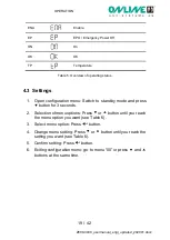
Page 19: ...ation menu Switch to standby mode and press button for 3 seconds 2 Selection of menu options Press or button until you reach the menu option you want see Table 6 3 Select menu option Press button 4 Change menu setting Press or button until you reach the setting you want see Table 6 5 Confirm setting Press button 6 Exiting configuration menu go to menu 00 or press and buttons at the same time ...

Page 20: ...t sockets active and UPS system re started after setting the time 999 Battery deep discharge protection Shutdown of all output sockets in battery mode after time defined here 0 999 Shutdown after 0 to 999 minutes DIS Shutdown time dependent on bat tery capacity Attention If the setting is 0 shutdown is after 10 seconds DIS Emergency power off function AO active open emergency power off is active w...

Page 21: ...ected is supplied with power Battery mode In battery mode the following display appears Figure 16 Battery mode display At the same time an acoustic alarm every 5 seconds indicates that the load connected is being supplied with battery power If the battery charge is low in battery mode the display shows BL starts flashing and the alarm sounds every 2 seconds The remain ing autonomy time is low Clos...

Page 22: ...de The following display appears Figure 17 Display in standby mode No power is available for the load connected The battery is charged if necessary Buck Boost mode If the input voltage is greater than the maximum tolerance the UPS system switches into buck mode The output voltage is reduced to a non critical level electronically without using the batteries Figure 18 Display Buck Boost mode display...

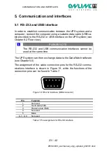
Page 23: ...apter 8 2 Rear view PLEASE NOTE The RS 232 and USB communication interfaces cannot be used at the same time The UPS system can then exchange data via the DataWatch software see Chapter 5 5 The assignment of the cable connection pins for the RS 232 commu nications interface is shown in Figure 19 while the functions of the connection pins can be found in Table 7 Figure 19 RS 232 interface DB9 connec...

Page 24: ... use of relay contacts The following mes sages contact outputs are available UPS normal mode standby mode battery mode battery voltage low bypass mode XANTO only aggregated error input for UPS shutdown Table 8 Interface cards PLEASE NOTE The interface cards installed in the slot can be used in parallel with the RS 232 or USB communication 5 3 Emergency Power Off EPO function The Emergency Power Of...

Page 25: ...of the UPS system also needs to be interrupted The emergency power off function is only used to shut down the UPS voltage on an electronic basis PLEASE NOTE Leave the plug of the UPS system connected if you do not need the emergency power off function Always test the emergency power off function before connect ing a critical load This avoids the load being switched off ac cidentally Figure 20 Emer...

Page 26: ...lications and the proper shutdown of the whole system by means of a freely configurable shutdown routine At the same time DataWatch has a comprehensive messaging system time controlled test routines and event logging DataWatch supports all current operating systems As a client server application DataWatch works in networks and on local workstations Based on optional RCCMD agent Remote Con sole Com...

Page 27: ...er shutdown via TCP IP X SNMP proxy agent X Send E Mail SMS broadcastmessages X Manual UPS 10s test X X Manual UPS fulltest X Auto UPS selftest X Enabe disable alarm for battery operation X X Enable disable all alarms X Reset UPS system to factory settings X Display alarm warning and error messages X X Chronological record display and export csv of warning alarm and error messages X Record display...

Page 28: ...off The service life of a battery varies as a function of how often it is used intensity of use and ambient temperature Batteries which are used beyond their expected service life often have reduced autonomy times Replace the batteries in good time to ensure the system always runs at optimum performance 6 2 Storage If you intend to store the UPS system for an extended period charge the battery eve...

Page 29: ...ssary safety measures Do not allow unauthorised personnel to handle the batteries Batteries pose the risk of an electric shock or injury due to high short circuit current Take the following safety measures o remove watches jewellery and other metal items o only use tools with insulated handles o do not place tools or metal components on the batteries The batteries must only be replaced with the sa...

Page 30: ... system are very heavy Be careful when handling heavy batteries The batteries are behind the front panel of the UPS system The inter nal batteries are packed together for ease of handling 1 Remove the front panel see Figure 21 To do this pull the frontpanel to the front side of the UPS system Figure 21 Removing the front panel PLEASE NOTE There is a flat ribbon cable connecting the control panel t...

Page 31: ...3 Figure 23 Removing the battery cover 4 Carefully remove the battery insert using the handle 5 Replace the batteries in the battery insert PLEASE NOTE Check that the replacement batteries have the same specifi cations as the old batteries Read Chapter 6 6 Disposing of the old batteries or UPS sys tem for information on proper disposal 6 Reverse the removal procedure to reinsert the battery insert...

Page 32: ...rnings Press OK to acknowledge a suc cessful battery test and to switch the UPS system back into nor mal mode PLEASE NOTE The UPS system only starts a self test when the batteries are fully charged and the UPS system is in normal mode with no active warning messages 6 6 Disposing of the old batteries or UPS system Find out from a local recycling centre how the old batteries or the UPS system shoul...

Page 33: ... circuit in inverter output 27 Battery voltage too high 28 Battery voltage too low 41 Temperature too high 43 Overload 45 Charger error Table 10 Error codes If the UPS system indicates one of the error codes listed above please contact ONLINE support see Chapter 7 5 7 2 Warnings Event Symbol Code Alarm Battery capacity low Warning sound every 2 seconds Overload Warning sound every sec ond Battery ...

Page 34: ...power off is active Check that the emer gency power off con nector is seated firmly and the wire jumpers match the menu settings in Chapter 4 3 closed or open depending on the jumper Then press the OFF button for 2 seconds and start the UPS system using the ON button The and symbols flash and an alarm is sounded every 2 seconds The internal battery is not connected Check that the battery is proper...

Page 35: ...he alarm In battery mode hold the ON button for at least 2 seconds to mute the alarm Once the alarm is successfully muted appears in the display Check the status the warning message has triggered and take appropriate measures to rectify the situation If the status of the warning message changes the alarm is emitted again This has prior ity over the previous muting of the alarm PLEASE NOTE The alar...

Page 36: ...ter purchase ONLINE sets great store by reliable support and service Free direct advice and support on Software hotline 49 89 242 39 90 13 Hardware hotline 49 89 242 39 90 18 Free 24 h advance exchange Interactive UPS configurator online or as app 2 years full warranty optional renewal Unbureaucratic 14 day money back guarantee Excellent product availability and wide network of distributors Furthe...

Page 37: ...Hz Input current 6 0A 7 4A 11 0A 14 9A 17 6A Output voltage 230V adjustable to 208 220 230 240V Output voltage tolerance battery operation 3 Output frequency normal operation 50 60H 1Hz Power loss max 88W 110W 165W 220W 330W Output current max 4 2A 5 3A 7 9A 10 6A 15 9A Switchover time Type 2 6ms Wave form Sine Efficiency Normal operation 97 Buck Boost mode 95 Battery mode 89 91 92 Overload compat...

Page 38: ...A Charging time 6 hours to 90 Communication USB Yes RS 232 Yes Modem Network Over voltage protection Yes SNMP slot Yes EPO Yes Operating conditions standards and approvals Operating temperature 0 40 C Rel air humidity 0 90 Noise level Normal mode max dBA Silent 45 dB MTBF at 25 C w o battery 50 000 hours Safety EN62040 1 EMC Performance EN62040 2 EN61000 2 2 EN61000 3 2 EN61000 4 2 EN61000 4 3 EN6...

Page 39: ...TECHNICAL DATA 39 42 Z800 3000_usermanual_engl_updated_202001 docx 8 2 Rear view Figure 24 Rear view of ZINTO 800 1500 Figure 25 Rear view of ZINTO 2000 ...

Page 40: ...TECHNICAL DATA 40 42 Z800 3000_usermanual_engl_updated_202001 docx Figure 26 Rear view of ZINTO 3000 ...

Page 41: ...TECHNICAL DATA 41 42 Z800 3000_usermanual_engl_updated_202001 docx 8 3 CE confirmation ...

Page 42: ...d Apart from the above exceptions ONLINE accepts no explicit or tacit warranty including a guarantee of conventional quality or suitability for a specific purpose In some jurisdictions the restriction or exclusion of tacit guarantees is prohibited which means that the restrictions or ex clusions above may not apply to the purchaser Irrespective of the above exclusions ONLINE shall under no circum ...

Reviews: