background image


24


Connecting Your  Components


—Continued


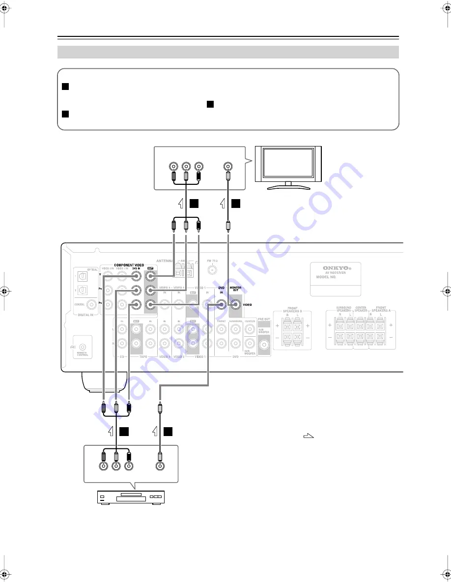
Connecting a DVD Player

Y

P

B

COMPONENT VIDEO OUT

P

R

VIDEO

OUT

Y

P

B

COMPONENT VIDEO IN

VIDEO IN

P

R

A

B

B

B

A

B

TV, projector, 
etc.

DVD player

AV receiver

Step 1: Video Connection (DVD Player to AV Receiver to TV)

If your TV has component video input jacks, connect your DVD player to the AV receiver’s COMPONENT 
VIDEO DVD IN jacks. And connect the AV receiver’s COMPONENT VIDEO OUT jacks to your TV. This will 
provide better picture quality than connection 

.

If your TV doesn’t have component video input jacks, connect your DVD player to the AV receiver’s DVD IN 
VIDEO jack. And connect the AV receiver’s MONITOR OUT VIDEO jack to your TV.

A

B

B

: Signal Flow

TX-SR304̲En.book Page 24 Tuesday, February 7, 2006 4:57 PM

Summary of Contents for TX-SR304

Page 1: ...lowing the instructions in this manual will enable you to obtain optimum performance and listening enjoyment from your new AV Receiver Please retain this manual for future reference Contents Introduct...

Page 2: ...aratus does not operate normally by following the operating instructions Adjust only those controls that are covered by the operating instructions as an improper adjustment of other controls may resul...

Page 3: ...or a long time because they may leave marks on the case This unit s top and rear panels may get warm after prolonged use This is normal If you do not use this unit for a long time it may not work prop...

Page 4: ...to charge the backup system Once it has been charged the AV receiver will retain the settings for several weeks although this depends on the environment and will be shorter in humid climates Supplied...

Page 5: ...od Late night mode 3 Mode display dimmer Full Function RI remote control Contents Important Safety Instructions 2 Precautions 3 Supplied Accessories 4 Features 5 Front Rear Panels 6 Before Using the A...

Page 6: ...rce H DIGITAL INPUT button 33 53 This button is used to assign the digital inputs and to specify the format of digital input signals I DIMMER or RT PTY TP button 41 42 This button is used to adjust th...

Page 7: ...tton selects the DVD analog multichannel input R RETURN button 34 48 51 This button is used to return to the previously dis played setup menu S SETUP button 34 48 51 This button is used to access vari...

Page 8: ...ake an analog audio connec tion RCA between the AV receiver and the other component even if they are connected digitally Note can only be used with Onkyo components I CD IN These analog inputs can be...

Page 9: ...ntroller of the same type is used in the same room or the AV receiver is installed close to equipment that uses infrared rays the remote control ler may not work reliably Don t put anything such as a...

Page 10: ...he AV receiver To set the remote controller to RECEIVER mode press the RECEIVER REMOTE MODE button How to Use the Remote Controller 1 Use the REMOTE MODE buttons to select a mode 2 Use the buttons sup...

Page 11: ...ects the Stereo listening mode SURROUND button This button selects the Dolby and DTS listening modes buttons These buttons can be used to select any of the avail able listening modes J TEST TONE CH SE...

Page 12: ...s button is used to display information about the current disc title chapter or track on the DVD player s display including the elapsed time remain ing time total time and so on K CLR button This butt...

Page 13: ...ing time total time and so on F CLR button This button is used to cancel functions and to clear entered numbers G RANDOM button This button is used with the random playback func tion H REPEAT button T...

Page 14: ...to clear entered numbers F RANDOM button This button is used with the random playback func tion G REPEAT button This button is used to set the repeat playback func tions H PLAY MODE button This button...

Page 15: ...ent s menu buttons Select options on the HDD component s menu ENTER button Confirms the selection on the HDD component s menu G RANDOM button This button is used with the random playback func tion H R...

Page 16: ...rt reverse playback D Rewind FF buttons The Rewind button is used to start rewind The FF button is used to start fast forward TAPE Mode TAPE 7 To select your Cassette deck as the input source press RE...

Page 17: ...ner at about ear level and equally spaced from the TV Angle them inward Surround left and right speakers These speakers are used for precise sound position ing and to add realistic ambience Position t...

Page 18: ...label to the corresponding speaker terminal Read the following before connecting your speakers You can connect speakers with an impedance of 6 ohms or higher If you use speakers with a lower impedanc...

Page 19: ...ould be connected to each pair of terminals Connecting Speaker 1 Strip 3 8 10 mm of insu lation from the ends of the speaker cables and twist the bare wires tightly as shown 2 While pressing the lever...

Page 20: ...tune into an FM radio station and adjust the position of the FM antenna to achieve the best possible reception 2 Fully extend the antenna and point it in various directions to find the best recep tio...

Page 21: ...h local regulations to prevent electrical shock haz ards Using a TV FM Antenna Splitter It s best not to use the same antenna for both FM and TV reception as this can cause interference problems If ci...

Page 22: ...ctions Left white Right red Yellow Analog audio Composite video Left white Right red Yellow Right Wrong Video Cable Jack Description Component video cable Component video separates the luminance Y and...

Page 23: ...you connect your DVD player to the COMPONENT VIDEO DVD IN a video signal will be output by the COMPONENT OUT but not by any com posite video outputs Video Input Output Diagram Audio Connection Formats...

Page 24: ...TV If your TV has component video input jacks connect your DVD player to the AV receiver s COMPONENT VIDEO DVD IN jacks And connect the AV receiver s COMPONENT VIDEO OUT jacks to your TV This will pr...

Page 25: ...ssignment to OPT1 or OPT 2 see page 33 Coaxial connections perform the same as optical ones Optionally connecting your DVD player s audio out L R jacks to the AV receiver s DVD IN FRONT L R jacks will...

Page 26: ...eo output jacks to the AV receiver s COMPONENT VIDEO VIDEO 1 IN jacks and connect the AV receiver s COMPONENT VIDEO OUT jacks to your TV s component video in jacks This offers better picture quality t...

Page 27: ...jacks to your VCR s audio input jacks A a VCR DVD recorder AV receiver Signal Flow Connecting a Camcorder Games Console or Other Device AUDIO OUT L R VIDEO IN VIDEO OUT a A Step 1 Video Connection Co...

Page 28: ...than composite video Connect a coaxial feed from a TV antenna to your set top box s antenna input jack e g RF IN and connect your set top box s antenna output jack e g RF OUT to your TV s antenna inp...

Page 29: ...ur turntable with built in phono preamp s audio output jacks to the AV receiver s CD IN L R jacks With connection you can listen to and record audio from the CD player or turntable If your CD player h...

Page 30: ...L R S VIDEO OUT To TV directly Connect one or the other AV receiver Signal Flow Connecting a Cassette CDR MiniDisc or DAT Recorder COAXIAL OUT OPTICAL OUT OUT PLAY L R IN RED L R a a b c Cassette reco...

Page 31: ...only cables for connections cables are supplied with Onkyo players DVD CD etc Some components have two jacks You can connect either one to the AV receiver The other jack is for connecting additional c...

Page 32: ...ss the STANDBY ON button or the remote control ler s ON STANDBY button The AV receiver will enter Standby mode To prevent any loud surprises the next time you turn on the AV receiver always turn down...

Page 33: ...ent DVD COAX VIDEO 1 VCR VIDEO 2 OPT 1 VIDEO 3 TAPE CD OPT 2 1 Press the input selector button for the source that you want to assign Digital inputs cannot be assigned to the TUNER input source 2 Pres...

Page 34: ...LEVEL LEVEL L NIGHT VOL HDD CDR MD DVD RECEIVER CD 10 0 CLR 1 2 3 4 5 6 7 8 9 ENTER CH DISC ALBUM RETURN 1 1 9 2 8 Speaker Configuration 1 Press the RECEIVER button fol lowed by the SETUP button 2 Use...

Page 35: ...s the SETUP button Setup closes When you want to go back up one menu level to SP Config press the RETURN button SETUP Testing the speakers To test that all of the speakers are working properly press t...

Page 36: ...et that you want to use Pressing the remote controller s SPA B button cycles through the following settings Speaker Set A Speaker Set A B Speaker Set B Off The A and B speaker indicators show whether...

Page 37: ...conds then the previous display reap pears Interpreting Surround Channel Information A The number of front channels front left front right and center B The number of surround channels surround left an...

Page 38: ...ning to the Radio 1 Use the TUNER input selector button to select either AM or FM In this example FM has been selected Actual display depends on country 1 Press the SETUP button to dis play 0 Hardware...

Page 39: ...ER CD MASTER VOLUME A SPEAKERS B 2 4 3 MEMORY TUNING PRESET ENTER MEMORY TONE STEREO LISTENING MODE DISPLAY DIGITAL INPUT RT PTY TP MEMORY TUNING MODE RETURN TUNING PRESET ENTER SETUP STANDBY STANDBY...

Page 40: ...from an RDS station is weak RDS data may be displayed intermittently or not at all Program Types Used in Europe PTY RDS indicator Type Display Description None NONE No program type News reports NEWS...

Page 41: ...ODE RETURN TUNING PRESET ENTER SETUP STANDBY STANDBY ON CLEAR PHONES MULTl CH DVD VIDEO 1 VCR VIDEO 2 VIDEO 3 TAPE TUNER CD MASTER VOLUME A SPEAKERS B 2 1 3 5 TUNER RT PTY TP TUNING PRESET ENTER 4 To...

Page 42: ...dB in 2 dB steps Treble You can boost or cut high frequency sounds output by the front speakers from 10 dB to 10 dB in 2 dB steps Note To bypass the bass and treble tone circuits select the Direct li...

Page 43: ...ller s MUTING button The output is muted and the MUTING indicator flashes on the display as shown MUTING PREVIOUS MENU GUIDE TOP MENU SP A B SETUP RETURN PLAYLIST PLAYLIST RANDOM SUBTITLE PLAY MODE AU...

Page 44: ...the AV receiver is set to Standby Multichannel DVD Input While the multichannel DVD input is selected you can adjust the level of each 5 1 channel input individually from 12 dB to 12 dB 30 to 12 dB f...

Page 45: ...Dolby Digital and DTS listening modes can only be selected if your DVD player is connected to the AV receiver with a digital audio connection coaxial or optical Listening mode availability depends on...

Page 46: ...ar the DTS logo Neo 6 This mode provides 5 1 channel playback from 2 chan nel sources It offers five full bandwidth channels with excellent separation There are two modes of operation Cinema mode for...

Page 47: ...han Direct and Stereo Dolby D DTS DTS 96 24 2 2 DTS 96 24 is always processed as DTS Multich 2 2 0 Stereo 1 0 1 1 Other 3 2 1 2 0 Stereo DTS ES Discrete Matrix Source Listening mode CD TV VHS MD turnt...

Page 48: ...is output R Only the right channel is output Using the Audio Adjust Functions 1 Press the RECEIVER button fol lowed by the SETUP button MUTING PREVIOUS MENU GUIDE TOP MENU SP A B SETUP RETURN PLAYLIST...

Page 49: ...ound sound from 2 channel stereo sources With this setting you can specify by how much the front left and right channel output is attenuated in order to create the center channel It can be adjusted fr...

Page 50: ...tch the video from theVIDEO 3 input and listen to the audio from the CD input In the following example audio from the CD player con nected to the CD IN jacks and video from the camcorder connected to...

Page 51: ...SETUP button 2 Use the Up and Down buttons to select 1 SP Config and then press ENTER 3 Use the Down button to select Crossover and then use the Left and Right but tons to select a crossover fre quenc...

Page 52: ...Down buttons to select 2 SP Dis tance and then press the ENTER button 4 While Unit is displayed use the Left and Right buttons to select feet or meters feet Distances in feet Can be set from 1 to 30 f...

Page 53: ...vel and use the Down but ton to select the next speaker The level can be adjusted from 12 to 12 dB in 1 dB steps 15 to 12 dB for the subwoofer 5 Repeat step 4 so that the level of the test tone from e...

Page 54: ...utton 2 Press and hold for more than 4 seconds the input selector but ton for the input source that you want to correct This can be the DVD VIDEO 1 VIDEO 2 or VIDEO 3 input source 3 Use the Left and R...

Page 55: ...e doesn t have a phono preamp built in you must connect one between it and the AV receiver If your turntable uses an MC cartridge you must con nect an MC head amp or an MC transformer and a phono prea...

Page 56: ...level sampling rate or frequency response changed and the AV receiver doesn t recog nize it as a genuine DTS signal In such cases you may hear noise When playing DTS program material using the pause...

Page 57: ...must make an connection and an analog audio connection RCA between the compo nent and AV receiver even if they are connected digi tally page 31 Recording Others The AV receiver contains a microcompute...

Page 58: ...ent 0 7 Vp p 75 Component PB CB PR CR 1 Vp p 75 Composite Component Video Frequency Response 5 Hz 50 MHz Tuning Frequency Range North American 87 5 MHz 107 9 MHz European 87 50 MHz 108 00 MHz Asian 87...

Page 59: ...59 Memo...

Page 60: ...6 82194 Groebenzell GERMANY Tel 49 8142 4401 0 Fax 49 8142 4401 555 http www eu onkyo com ONKYO EUROPE UK Office Suite 1 Gregories Court Gregories Road Beaconsfield Buckinghamshire HP9 1HQ UNITED KING...

Reviews: